| John Broskie's Guide to Tube Circuit Analysis & Design |
05 Sept 2023 Post Number 587
Making something complicated is easy. Making something as simple as possible—without also making sacrifices—is difficult, if not supremely difficult. Examples abound. It is easier to design a decent three-way or four-way loudspeaker than a decent two-way speaker. (If cost and size restrictions didn't apply, few two-way speakers would exist, as mating a big woofer with a little tweeter makes little sense, the disparity in size, frequency limits, and power-handling ability being too great.)
Tube-based audio circuits are often quite simple, especially when compared to equivalent solid-state circuits. This is partially due to a long established practice that dates back to 100 years ago, when each handmade vacuum tube cost a fortune, but is mostly due to the triode's inherent good performance, the result of its exhibiting plate resistance, a form of built-in negative feedback.
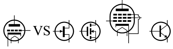
The triode is special, differing radically from the FET, MOSFET, pentode, or transistor. These alternative devices all exhibit such high collector, drain, and plate resistances that this high resistance can be safely ignored, as changes in their collector, drain, and plate voltages leave their current flow unaltered. In contrast, a triode's plate voltage, like its grid and cathode voltages, controls the amount of current flow from cathode to the plate. Increase a triode's plate voltage and it draws more current; decrease it, less current. The plate is 1/mu as effective as the grid, where mu stands for the triode's amplification factor; the cathode is mu + 1 times as effective as the grid. The "+ 1" comes from the plate-to-cathode voltage necessarily changing when we alter the cathode voltage. Thus, the lower the triode's mu, the greater the plate's effect on its current flow.
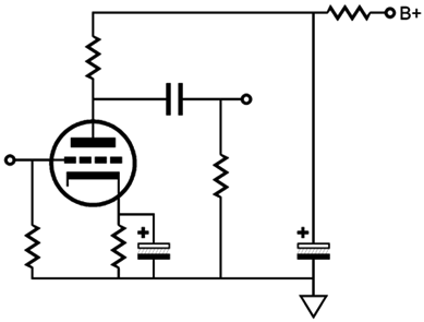
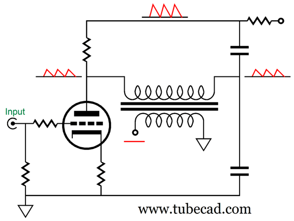
Pause to reflect how amazing it is that we can build a serviceable line-stage amplifier from a single low-mu triode tube, such as a 6J5WGT or 12B4 or 300B. One triode, three capacitors, five resistors—that is not much. We can add a grid-stopper resistor, but that doesn't complicate the circuit all that much; in fact, we can forgo the cathode's bypass capacitor. One workaround that I have presented before was to use an input signal transformer to enhance the grounded-cathode amplifier's PSRR. Here is an example circuit from post 328.
Note that resistor R2 breaks the connection to ground, so the transformer's secondary and the volume potentiometer are left floating. Here is my description of my circuit from that post:
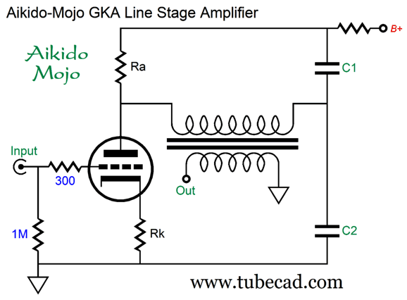
Another enhanced-PSRR arrangement would be to place the signal transformer at the output.
If the plate resistor's resistance equals (mu + 1)Rk + rp, then the grounded-cathode amplifier's PSRR will be -6dB, which means that 50% of the power-supply noise will appear at the triode's plate. In this case, we make C1 and C2 the same value, as the two capacitors will define a 50% voltage divider. The result is that the leaked power-supply noise is equal in magnitude on both terminals of the transformer's primary; therefore, the power-supply noise falls out of the equation.
On the other hand, if the cathode resistor is bypassed with a large valued capacitor, then the ratio between C1 & C2 must be altered until a deep PSRR null obtains. Note how capacitors C1 & C2 perform double duty, as they not only enhance PSRR but they also provide RC filtering due to the resistor that is in series with the B+ voltage. Of course, electrolytic capacitors can be used, but they should be measured for a tight match, as the typical tolerance is only 20%. The obvious downside to these circuits is that they require an expensive signal transformer. Well, this got me thinking about how by adding a second triode we could achieve the same improvement in PSRR.
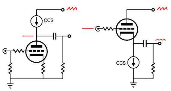
Well, why not exploit this situation. For example, we can use this leaked power-supply noise to create a power-supply-noise null.
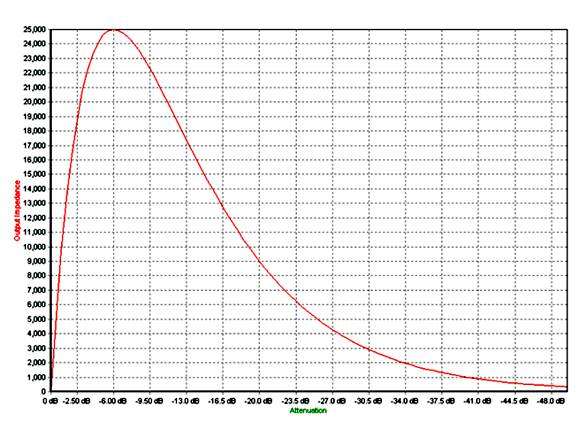
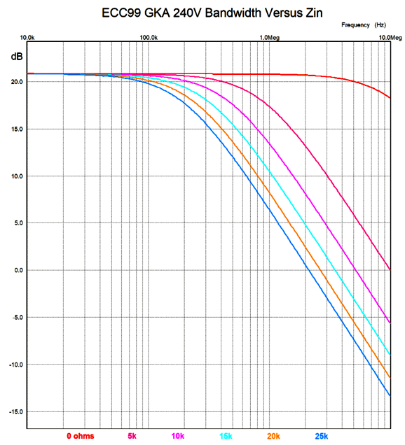
Adding a cathode follower in front of a grounded-cathode amplifier performs two tasks: it shields the signal source (and volume control potentiometer) from the triode's Miller-effect capacitance, and it leaks a small portion of the power-supply noise at the cathode follower's output. The first task ensures a wider—and consistent—bandwidth. How we get a wider bandwidth is obvious, but how we achieve consistent bandwidth takes some explaining. The volume control potentiometer, often 10k to 100k in resistance, will present its highest output impedance at the -6dB position, as one quarter of the potentiometer's resistance will be presented as the output impedance. For example, with a 100k potentiometer, that means at the 50% output (i.e. -6dB) position, the output impedance equals 25k. At lower and higher attenuation, the output impedance drops, realizing zero ohms at each extreme of shaft rotation.
The greater the input impedance, the more truncated the high-frequency bandwidth.
The cathode follower's output leaking some of the power-supply noise at its output seems altogether undesirable—at first. If we remember that the grounded-cathode amplifier both amplifies and inverts at its plate the signal at its grid, we can see how an optimal amount of leaked power-supply noise could be amplified to equal the power-supply noise leaking at the grounded-cathode amplifier's plate, thereby resulting in a null.
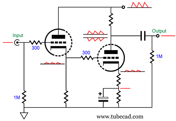
Here is one possible example circuit:
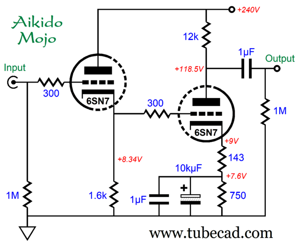
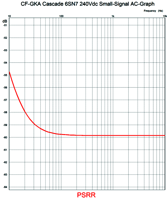
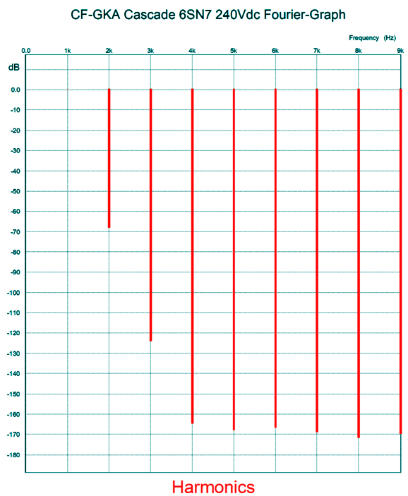
The trusty 6SN7 is used, and the cathode follower is directly coupled to the grounded-cathode amplifier. Two cathode resistors are needed—one to overcome the 8.34Vdc DC offset voltage and one to create just enough amplification to yield the desired power-supply-noise null at the plate. Normally, something like a 12µF bypass capacitor would be used with a 750-ohm cathode resistor, but to force the null to extend at least down to 100Hz, we need to use a much greater capacitor value. Since this capacitor will only see 7.6V of voltage, we can use a 10V or 16V capacitor. (The 1µF film bypass capacitor is there to help the electrolytic capacitor along; the -3dB low-frequency cutoff with a 1µF capacitor and 750-ohm resistor is 212Hz, by the way.) Here is the PSRR graph from SPICE simulation for this circuit.
The key frequency in countries with 50Hz AC wall voltage is 100Hz, which is the ripple frequency; with 60Hz wall voltage, 120Hz. The PSRR approaches -60dB. Bear in mind that -60dB means a 1000-fold reduction. My expectation was that the 2nd harmonic distortion would prove quite ripe, as the two circuits, cathode follower and grounded-cathode amplifier, operate in current phase, but not voltage phase. (Triodes are easier to turn on than to turn off, which gives them their strong 2nd harmonic characteristic.) Yet, the SPICE simulations revealed a respectable and not too fat cascade of harmonics with 1Vpk of output signal at 1kHz.
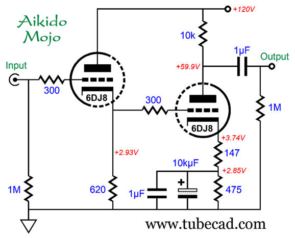
This translates in a THD below 0.1%. The gain is about 20dB (1:10); and the output impedance is about 6k. I love that this circuit could have been built 60 years ago, as no fancy solid-state circuitry is needed. A lower-voltage version can be made with the 6DJ8.
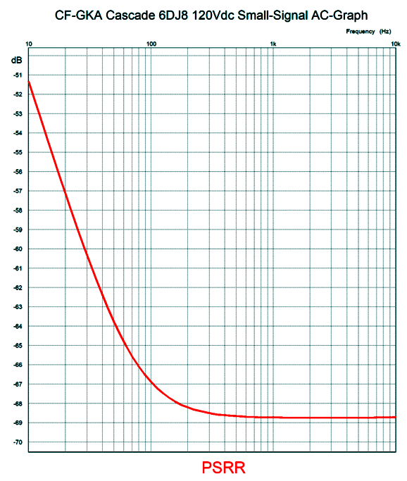
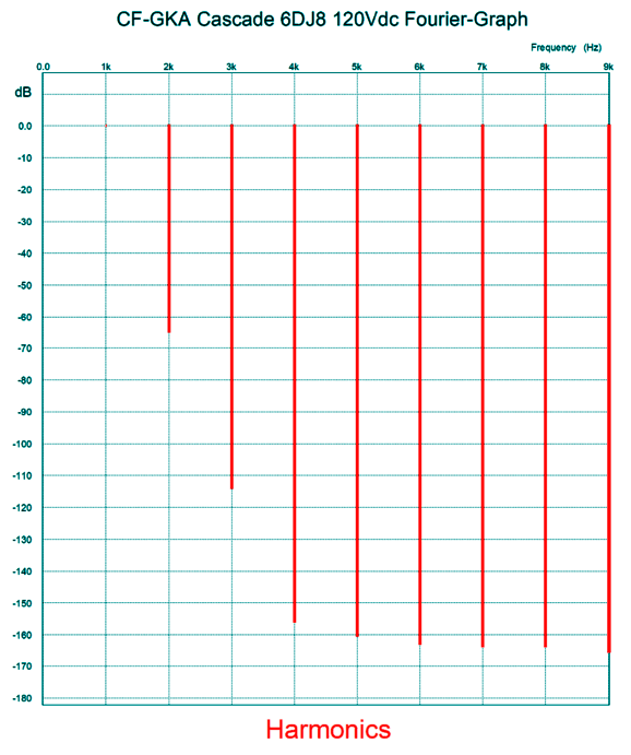
The 3.74Vdc cathode voltage allows us to use a 10kµF/6.3V bypass capacitor. The gain rises to 22.5dB (1 : 13.3) and the output impedance falls to about 5k. How well did this low-voltage version perform?
The PSRR is even better this time, but the distortion is slightly higher.
At below 0.1% with 1Vpk of output at 1kHz, isn't that much worse, when we consider the higher gain and lower plate resistor value. Another candidate is the JJ ECC99 dual-triode tube.
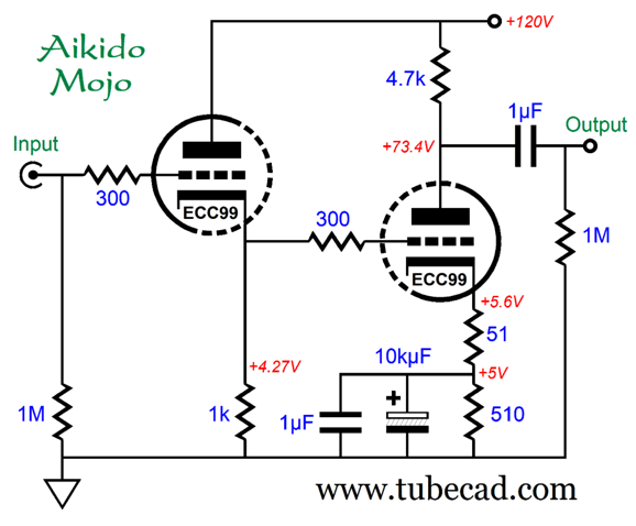
Note the much lower-resistance plate resistor, which implies a much higher idle current flow. The first thing that caught my attention was the 5V voltage drop across the 510-ohm cathode resistor, as my mind went instantly to this next variation.
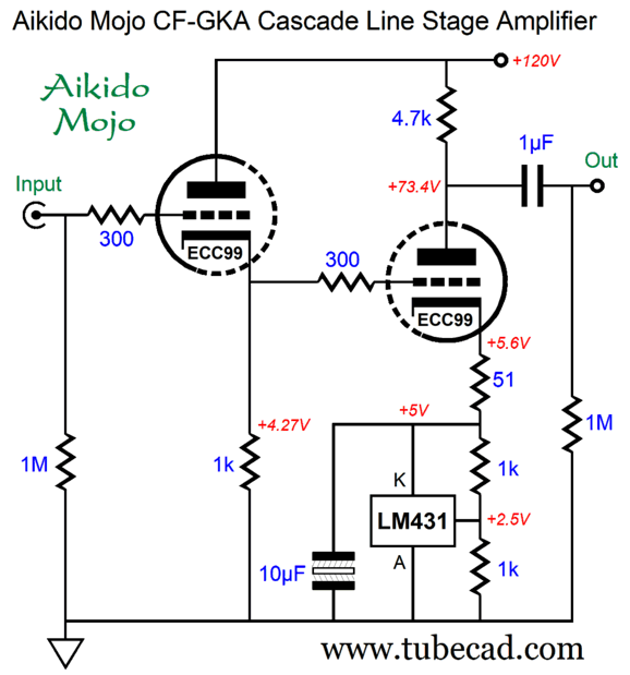
The LM341 (or TL431) is a shunt voltage regulator in a TO-92 package with just three leads. This solid-state IC zener replacement offers an adjustable break voltage and a very low output impedance (about 100 times lower than the 510-ohm cathode resistor). In other words, we will not need to use a 10kµF bypass capacitor. Instead, we can use a small non-polarized electrolytic capacitor.
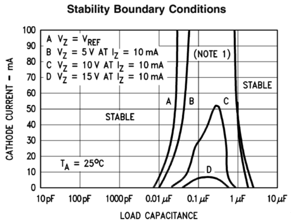
From the LM421 datasheet, we see that shunting capacitor values below 8.2nF and above 4.7µF are safe. Then, I wondered if this trip was really necessary. If we are striving for a low impedance, then nothing could beat ground.
The internal coupling capacitor can be much larger in value, as more capacitance will force the power-supply-noise null further down in frequency. Here is the SPICE-generated PSRR graph with the 1µF internal coupling capacitor.
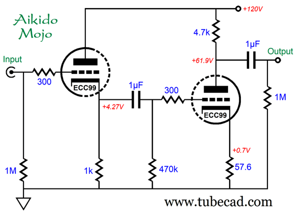
To get the null to extend further down in frequency requires a much larger-valued internal coupling capacitor, say 10µF. Why? Phase shift. Although a 1µF coupling capacitor terminating into a 470k grid resistor implies a -3dB down frequency of 0.33Hz, the phase shift at 100Hz is still too much for the deepest null. One possible workaround would be to use a 10µF non-polarized electrolytic capacitor in place of the film or PIO coupling capacitor. I expect that many will balk at this suggestion. Yet, these same audiophiles have no idea that their precious audio signal has already traveled through many polarized electrolytic capacitors in in their DACs and CD players and Tuners. (Ignorance is bliss, it seems.) Non-polarized electrolytic capacitors sound far better than polarized electrolytic capacitors, especially those made by either Panasonic or Nichicon. Normally, they cannot be used in tube-based circuits due to their relatively low voltage ratings. A low-voltage rating, however, is not an issue here. I wondered how well this variation would perform in the Fourier breakdown of harmonics test.
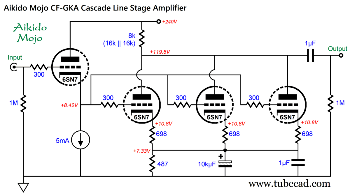
Quite well, it turns out. The THD is below 0.1% with 1Vpk output at 1kHz. The output impedance is about 2400 ohms. The 4.7k plate resistor may seem ridiculously too-low in value, but I chose it for two reasons: lower output impedance and higher idle current. Driving long interconnects takes current, as it takes current to quickly charge and discharge a heavy-capacitance load. Remember that slewrate equals: Slewrate = (2 × pi × Freq × Vpk) / 1,000,000 where the slewrate is in V/µS. And current equals slewrate against capacitance. I = Slewrate x Capacitance where slewrate is in V/µS and the capacitance is in µF. Solving for slewrate, we get: Slewrate = I/C The idle current through the grounded-cathode amplifier portion of this circuit is 12.4mA, which is plenty. Another way to increase the current flow through the plate resistor and to lower output impedance is to parallel triodes.
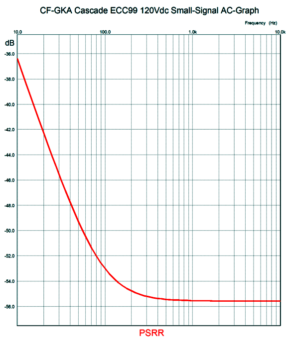
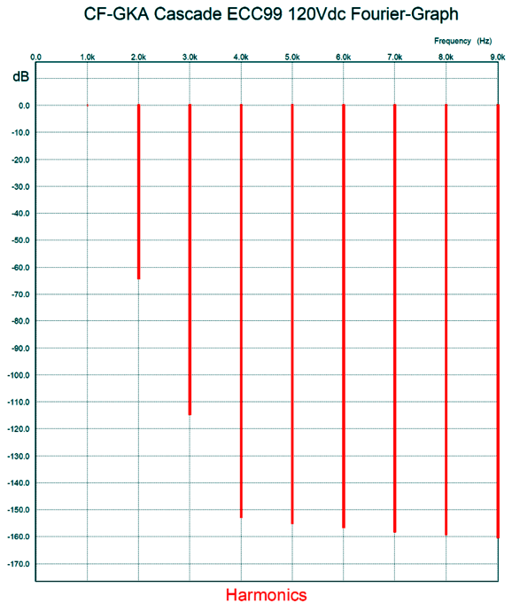
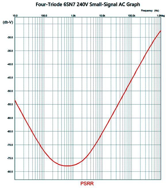
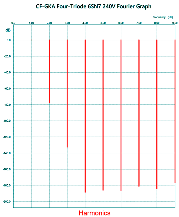
All the 6SN7 triodes draw 5mA. The 8k plate resistor is made up of two 16k resistors in parallel ("||" means in parallel). Here is the SPICE-generated PSRR graph:
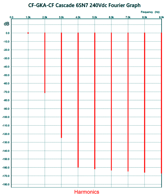
The Fourier graph follows:
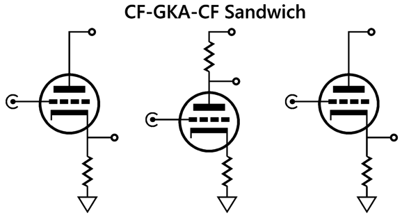
Another way to achieve a low output impedance would be to add an additional cathode follower to the circuit.
CF-GKA-CF Sandwich Line Amplifier
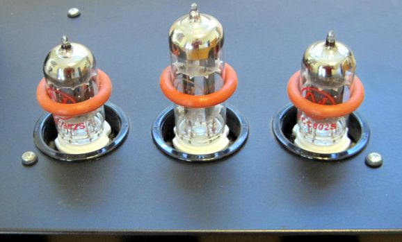
The only downside is that three twin-triode tubes will be needed to make a stereo line-stage amplifier. Three tubes, however, like other things in three (such as Cerberus and the Three Wise Men and Holy Trinity; Peter, Paul, and Mary; the Good, the Bad, and the Ugly), are cool.
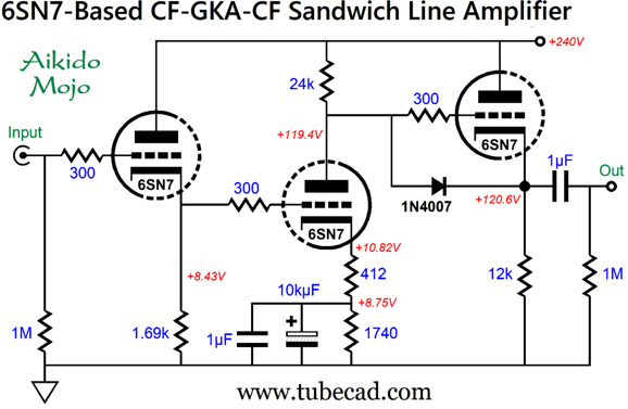
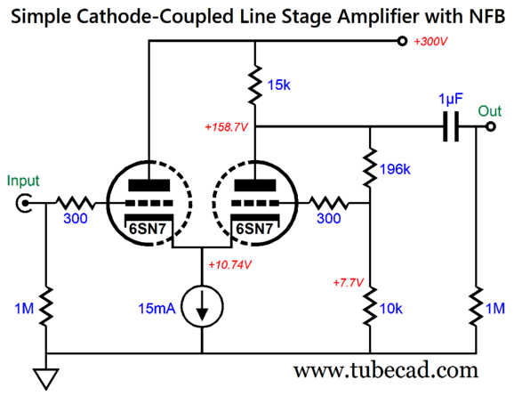
Imagine a sleek chassis with three tubes proudly protruding from its top panel, say two ECC802s flanking a center ECC99. (Speaking of thee tubes, I would love to build a monobloc single-ended power amplifier that three output tubes, with two smaller input and driver tubes in front.) It's true that three tubes will make point-to-point wiring a tad more difficult, but not impossible. Here is a simple, but effective, three-triode CF-GKA-CF line-stage amplifier.
The 1N4007 rectifier is there to protect the output cathode follower at turn on, as then is the only time the diode will be forward biased. The input cathode follower's and the grounded-cathode amplifier's 6SN7 triode idle at about 5mA, while the output cathode follower idles at 10mA. The PSRR null was impressive.
Without the added Aikido mojo, the PSRR would have been closer to -6dB. The distortion is wonderfully low.
With the sandwiched grounded-cathode amplifier free from having to do any work other than provide gain, the distortion falls to below 0.1%. Since the output cathode follower's cathode rest 120V above ground, we should voltage reference the heater power supply to 60Vdc, thereby splitting the difference. Alternatively, we could use a PS-21 or similar power supply with two regulated heater power supplies, giving one to the bottom triodes and the other to the top triodes. All-in-all, this looks like a fun project to build. Yet, I feel as I have deviated from the path of simple but effective. Thus, I went looking through my sketchpads for other two-triode designs that were both simple and effective.
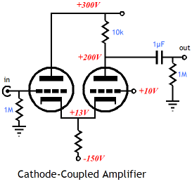
Simple Cathode-Coupled Amplifier
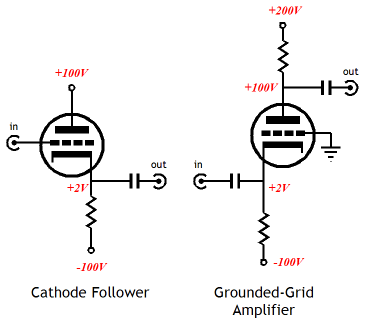
Since the cathode follower's output is its cathode, we can tie the two cathodes together, allowing us to use a shared cathode resistor. This resistor usually terminates into a high-voltage negative power-supply rail. We can, however, replace the shared cathode resistor with a constant-current source, thereby eliminating the need for a negative rail.
The following design differs from the usual grounded-grid amplifier in that both a constant-current source and that negative feedback are employed (both AC and DC).
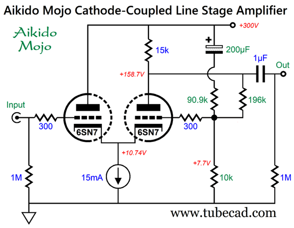
The input triode idles at 5mA, while the output triode idles at 10mA, which implies that both triodes will dissipate the same amount of heat. The discrepancy in grid-to-cathode voltages is overcome by the 196k and 10k two-resistor voltage divider, which serves a negative feedback loop, mainly DC negative feedback. The ratio of negative feedback resistors (196 + 10)/10 implies a gain of 1:21, which is not going to happen with a 6SN7 in this circuit. But in terms of DC negative feedback, the negative feedback loop works quite well at sending about twice the current flow through the 6SN7 triode on the right than through the one on the left. Where this design fails is at is in not delivering a decent PSRR, with its PSRR being only -4.2dB. Here is my Aikido mojo transformation.
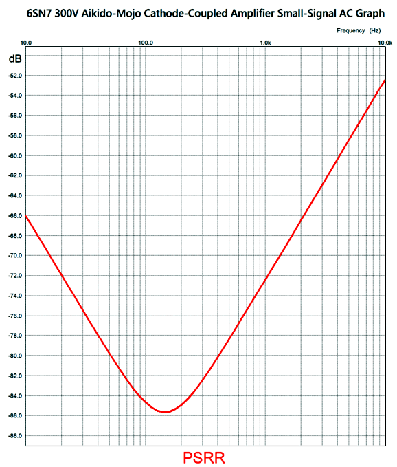
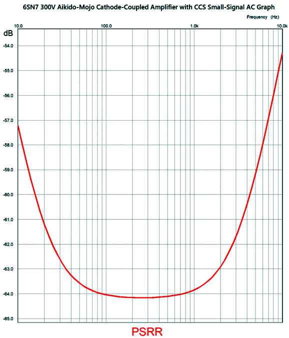
The same DC negative feedback obtains, but with the new signal path to the B+ voltage through the 90.9k resistor and 200µF capacitor, enough power-supply noise leaks to create a deep null.
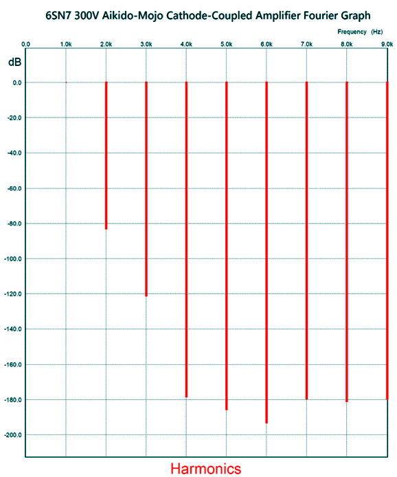
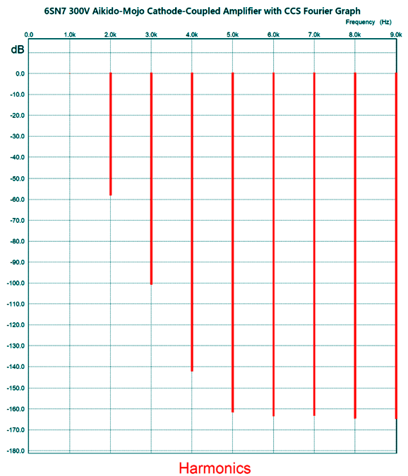
Wow! That's amazing. The Fourier graph was equally fine.
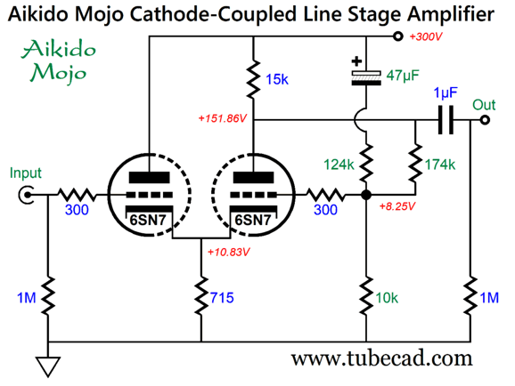
The THD is about 0.01%. Even if reality is ten times worse, the results are stellar. I wondered how much worse the circuit would be with a cathode resistor in place of the constant-current source.
The change in part values resulted in changes in operating voltages. The PSRR is good, but slightly less good as the CCS version.
This is a respectable PSRR. The distortion is also low.
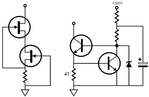
I would opt for the constant-current source version. The constant-current source could be made from a single FET or two LM334s in parallel or, even, an LM317 configured as a constant-current source. Or, we can get extra fancy:
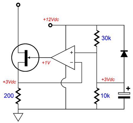
The zener in the circuit on the right is there to protect the transistors at turn-on when the tubes are cold and not yet conducting. Any zener voltage between 3V to 6.2V will work. The capacitor improves the PSRR of the circuit. If a 12Vdc heater power supply is used and if this power supply is grounded, we can terminate the two-resistor string into its 12Vdc, rather than the B+ voltage. Indeed, we could use this 12Vdc power-supply rail to power an OpAmp-based constant-current source.
Just about any FET can be used, but a low-noise, unity-gain, rail-to-rail OpAmp is needed, such as the LT1677, which can be powered even by a low 6.3Vdc power-supply rail.
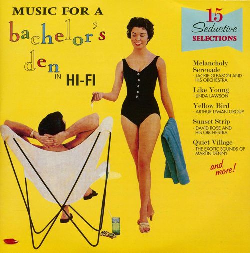
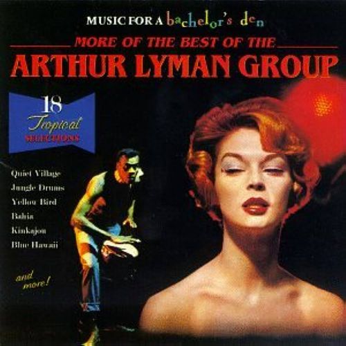
Music Recommendation: Space-Age Bachelor Pad Music Start with the span of years from 1955 to 1965, and then take the Space Age (1957), the development of stereophonic home-music reproduction (mid-1950s), and American 1950's lingering prosperity along with the advent of the birth control pill (1960)—combine them and you get Space-Age Bachelor Pad Music. (For my young readers, I must point out that this "pad" is not the pad of an iPad or female sanitary pad, but an apartment.) Imagine it's 1960 and you just bought a stereo phono cartridge, stereo power amplifier, and two big speakers. What are you going to listen to? Your old mono LPs? No, you would want new LPs that showed off your STEREO playback—good and hard. Separation, lots of it; punchy bass, lots of it; sparkling highs, lots of it. Space-Age Bachelor Pad Music was made with you in mind. The unspoken assumption here is that you are a red-blooded American male, which helps explain the babe-bejeweled covers of the genre.
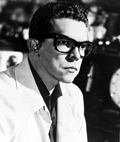
Back in the 1990s—the decade in which there was a move to redefine the word "bachelor" more inclusively (inspired no doubt by then president Bill Clinton) to "an unmarried or married man"—Juan García Esquivel was rediscovered. I wondered if The Bachelor, the American TV series, might have been spawned in the 1990s, but no; this crime against humanity came out in 2002.
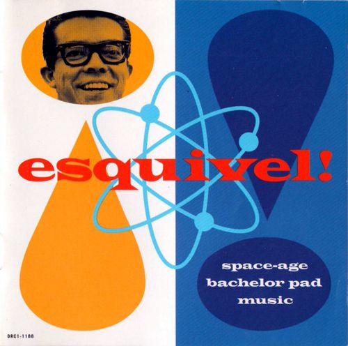
I like Esquivel! (the exclamation point became part of his name, rightly so), as his music not only showcases my stereo system, but is actually interesting to hear. Born in 1918 in Tampico, Mexico, Esquivel was crowned the King of Space-Age Pop music. Hard to describe, his music combines elements of jazz and Latin music with wordless singing and wild sound mixing. For example, he sometimes flips the channels mid track.
//JRB
Did you enjoy my post? Do you want to see me make it to post 1,000? If so, think about supporting me at Patreon.
User Guides for GlassWare Software
For those of you who still have old computers running Windows XP (32-bit) or any other Windows 32-bit OS, I have setup the download availability of my old old standards: Tube CAD, SE Amp CAD, and Audio Gadgets. The downloads are at the GlassWare-Yahoo store and the price is only $9.95 for each program. http://glass-ware.stores.yahoo.net/adsoffromgla.html So many have asked that I had to do it. WARNING: THESE THREE PROGRAMS WILL NOT RUN UNDER VISTA 64-Bit or WINDOWS 7, 8, and 10 if the OS is not 32-bit or if it is a 64-bit OS. I do plan on remaking all of these programs into 64-bit versions, but it will be a huge ordeal, as programming requires vast chunks of noise-free time, something very rare with children running about. Ideally, I would love to come out with versions that run on iPads and Android-OS tablets.
|
I know that some readers wish to avoid Patreon, so here is a PayPal button instead. Thanks.
John Broskie
John Gives
Special Thanks to the Special 85 To all my patrons, all 85 of them, thank you all again. I want to especially thank
All of your support makes a big difference. I would love to arrive at the point where creating my posts was my top priority of the day, not something that I have to steal time from other obligations to do. The more support I get, the higher up these posts move up in deserving attention.
If you have been reading my posts, you know that my lifetime goal is reaching post number one thousand. I have 419 more to go. My second goal was to gather 1,000 patrons. Well, that no longer seems possible to me, so I will shoot for a mighty 100 instead. Thus, I have just 18 patrons to go. Help me get there. Thanks.
Only $12.95 TCJ My-Stock DB
Version 2 Improvements *User definable Download for www.glass-ware.com
|
|||


| www.tubecad.com Copyright © 1999-2023 GlassWare All Rights Reserved |