| John Broskie's Guide to Tube Circuit Analysis & Design |
30 June 2023 Post Number 583
What to build? Isn't that the question that every audiophile who wields a soldering iron must answer? (Those who cannot solder must answer: What to buy?) The two big constraints, time and money, help to limit my choices—which I welcome. Having too many choices is only slightly preferable to no choices. In one of the few lovely passages in Immanuel Kant's writings, we find
Of course, the poor bird does not realize that without air resistance, it would plummet to the ground. Some opposition, resistance, strife, turmoil is essential, much as boat requires ballast—rather than just lifting an observation from Schopenhauer, I should quote him directly:
At the same time, I hate infinite opposition. (As so often proves to be the case, there is an optimal amount to everything, including resistance and ease.) When existence throws me a free bone, however, I am eager to jump on it.
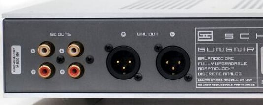
Here is an example: my DAC, a Schiit Gungnir revision-B multibit, sports both RCA and balanced outputs. In spite of my system not holding balanced power amplifiers, it's the two XLR output jacks haunt me, as a set of balanced output signals can prove extremely useful. How so? I can instantly think of three examples.
First Alternative Use of Balanced Signals
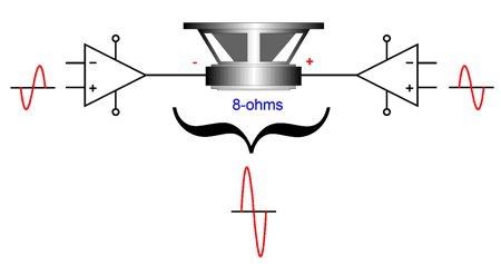
Second, balanced output signals allow us to use one unbalanced stereo power amplifier per channel, which results in a huge power increase, up to a fourfold increase when configured as a bridge amplifier.
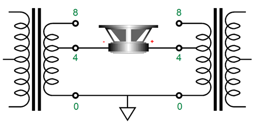
Well, this is true as long as the power amplifier does not hold an output transformer or a tube-based OTL output stage. Why? Bridge power amplifiers with output transformers only double the output power. With an transformer-coupled output stage, the amplifier is neither voltage nor current limited, but optimally configured to deliver both voltage and current into a specified load impedances; thus, the 4-ohm, 8-ohm, and 16-ohm output taps on the output transformer. An 8-ohm speaker can be attached across two 4-ohm taps, as each tap effectively sees a 4-ohm load impedance.
And tube-based OTL power amplifiers are so current limited that bridging their outputs can only yield a tiny power increase. In other words, OTL amplifier are already at their current limit; the only exception would be if a 16-ohm loudspeaker were driven, then we would expect the fourfold increase in output power. In contrast, with a stereo unbalanced solid-state power amplifier, the balanced input signals drive the two amplifiers in anti-phase, so we can attach the loudspeaker across the two outputs, with no connection to ground. If you double the output voltage swing across a loudspeaker, you end up delivering four times more power. The formula for AC power delivery is Wattage = (Voltage²/Rload)/2. Not all solid-state stereo power amplifiers, however, can develop twice the output voltage swing, as each amplifier effectively sees the loudspeaker's impedance halved. An 8-ohm loudspeaker appears as a 4-ohm speaker; a 4-ohm loudspeaker, as a 2-ohm load. This is an example of where reading the spec sheet comes in handy. For example, a stereo solid-state power amplifier that puts out 100W into an 8-ohm load might only be able to deliver 180W into a 4-ohm load, not the expected 200W. Thus, this amplifier arranged as a bridge amplifier will deliver 360W into an 8-ohm load. (Do not try this trick with 4-ohm loudspeakers, unless you know for certain that the amplifier can drive 2-ohm loads.) Nonetheless, 360W is a lot more than 100W. Asides from the big power increase, using one stereo solid-state power amplifier per channel prevents cross-talk between channels. By the way, the two stereo power amplifiers do not need to hold XLR input jacks, as two RCA jacks are all that is needed.
Second Alternative Use of Balanced Signals
Here is its description from the website:
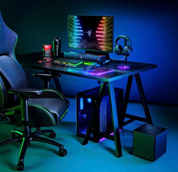
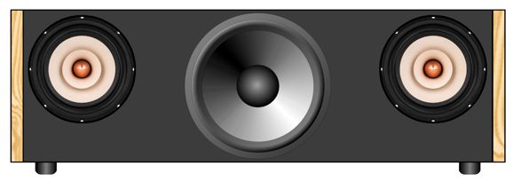
In contrast, what I am thinking of is a single, long loudspeaker enclosure that doubles as a monitor stand/riser. Think of a home theater center-channel soundbar, but instead of a tweeter flanked by woofers, we have a single woofer flanked by fullrange drivers, with all the driver driven by a built-in stereo power amplifier.
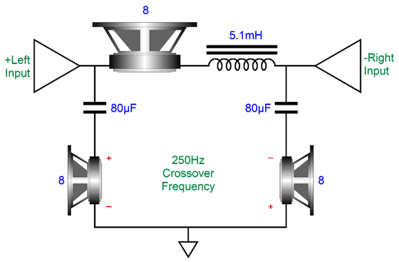
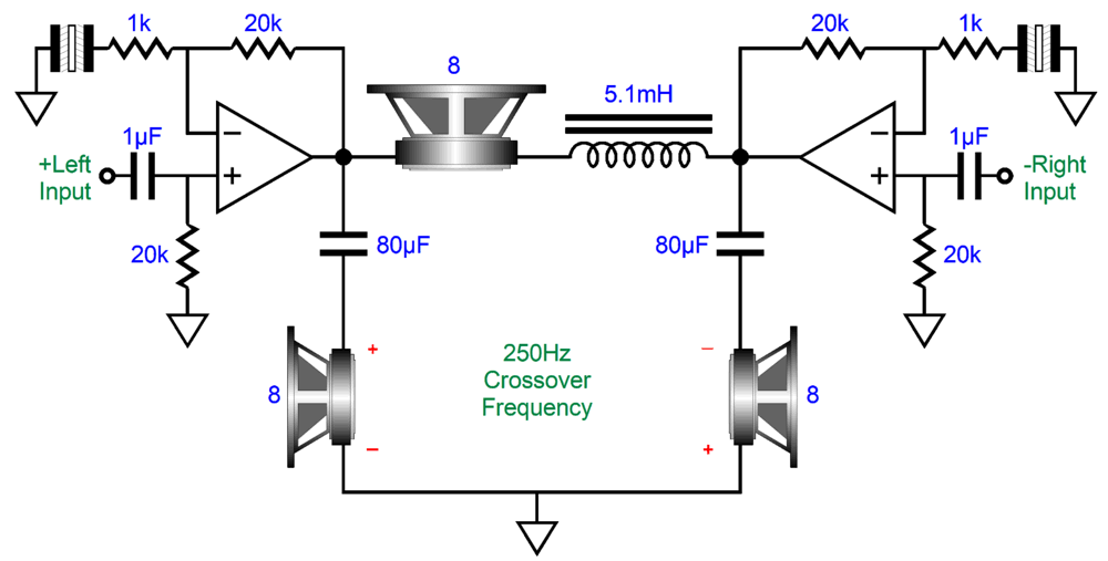
Now, for the interesting question: how do we power this stereo loudspeaker with just two power amplifiers? If the woofer holds two voicecoils, we have no problem, as we can use two conventional passive crossovers. What if the woofer holds only a single voicecoil? Well, here is where some thinking outside the box comes to the rescue. We can flip the phase on one channel, say the right channel, and then flip the phase on the right fullrange driver. Both fullrange drivers will now work in phase with each other. Next, we drive the single woofer in a bridge-amplifier configuration.
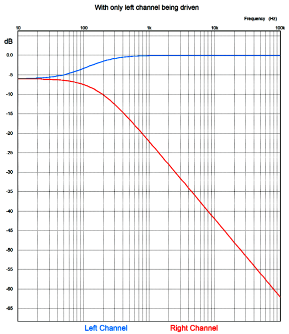
All drivers must share the same SPL efficiency. Only one woofer and one inductor are needed. If only the left channel presents audio signal, the left amplifier sees an 8-ohm load impedance. The 1st-order crossover results in a flat frequency and phase response.
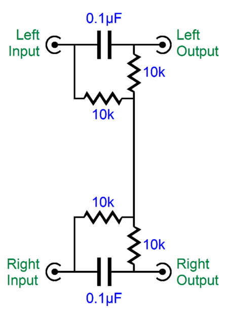
The right amplifier acts as 'virtual" ground for the woofer. In other words, even if only the left channel amplifier is delivering an output signal, both amplifier channels will get hot. In fact, the right amplifier will get hotter, paradoxically enough, as it output is centered, and so its output devices see the entire half of the bipolar power supply voltage, without the usual subtracting of the output voltage swing. Doesn't sound promising, does it? Well, the saving feature is that most recordings do not offer a great deal of separation of low-frequency signals, which mimics life in that low-frequencies are pretty much omnidirectional. Imagine recording a jazz quartet with two microphones; both microphones will pick up the deep bass frequencies. We can force mono bass frequencies by adding the following circuit.
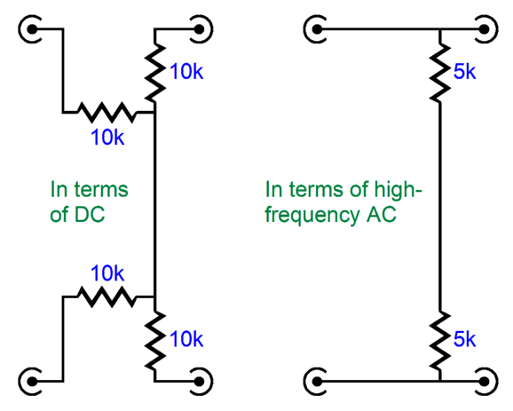
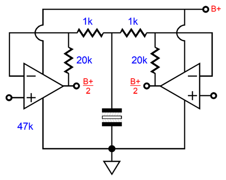
Only the bass signals are blended. The transition frequency for this example is about 160Hz. If it does not seem to make sense, let's look at two extremes: DC and ultra-high frequencies.
At DC, the two coupling capacitors are open circuits, so the DC mixes by 100%—or rather, it blends by averaging the two DC voltages. For example, if the left input signal is 1Vdc and the right is 0Vdc, then both amplifiers will see 0.5Vdc as input signal. If both the left and right input signals are 1Vdc, then both amplifiers will see 1Vdc as input signal. At ultra-high frequencies, the two coupling capacitors are effectively dead shorts. If the left channel's AC signal is 1Vpk at 10kHz and no signal appears in the right channel, then the left power amplifier will see 1Vpk, while the right power amplifier will see 0V. I doubt that this circuit is actually required, but experimentation is always welcome. My motivation for coming up with this modified bridge amplifier topology was to do away with large output coupling capacitors for the woofers in a monopolar-power-supply arrangement.
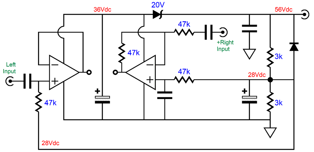
Desktop switching power supplies are here to stay, so we might as well exploit them. The small problem is that bipolar switching power supplies are relatively rare (and expensive). In my closet, sits a huge array of monopolar switching power supplies, ranging from 5Vdc to 56Vdc. In contrast, a single large-valued power-supply reservoir capacitor can easily cost more than any of my switchers. Returning to the schematic, we see that the B+ voltage is halved by the two 3k resistors and their output reference voltage is smoothed by the electrolytic capacitor. Since the single woofer and its low-pass inductor bridge the two outputs, no large-valued coupling capacitor is needed. The only aspect that I must stress is that one channel's input signal must be inverted relative to the other's input signal. With balanced outputs coming from the DAC, this is not a big deal. If an unbalanced input signal source is used, it becomes a problem. The workaround is to add an OpAmp input stage that will invert the right channel's input signal.
With a B+ voltage of only 30Vdc, we can get away with any unity-gain stable dual OpAmp that sound good. With a B+ voltage of 56Vdc, however, we must find a suitable high-voltage OpAmp. Or, must we? We could place a zener in series with the OpAmp's B+ voltage.
The 20V zener displaces enough voltage to provide a safe 36Vdc, the equivalent of a ±18Vdc bipolar power supply. The OpAmps need only to output a volt or two, as both are configured for unity-gain output. By the way, since the OpAmps already offer outputs centered at half the power amplifier B+ voltage, we can directly attach the OpAmps to the power amplifiers.
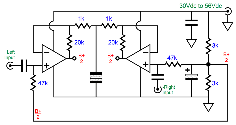
Okay, as I cannot look upon any circuit without thinking up an alternative. Here is my latest variation on the OpAmp solution.
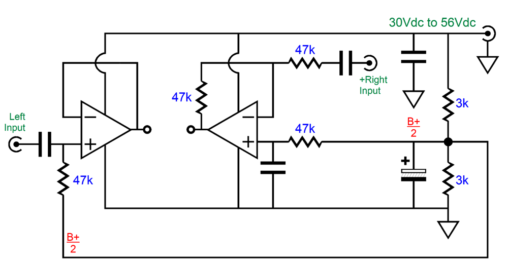
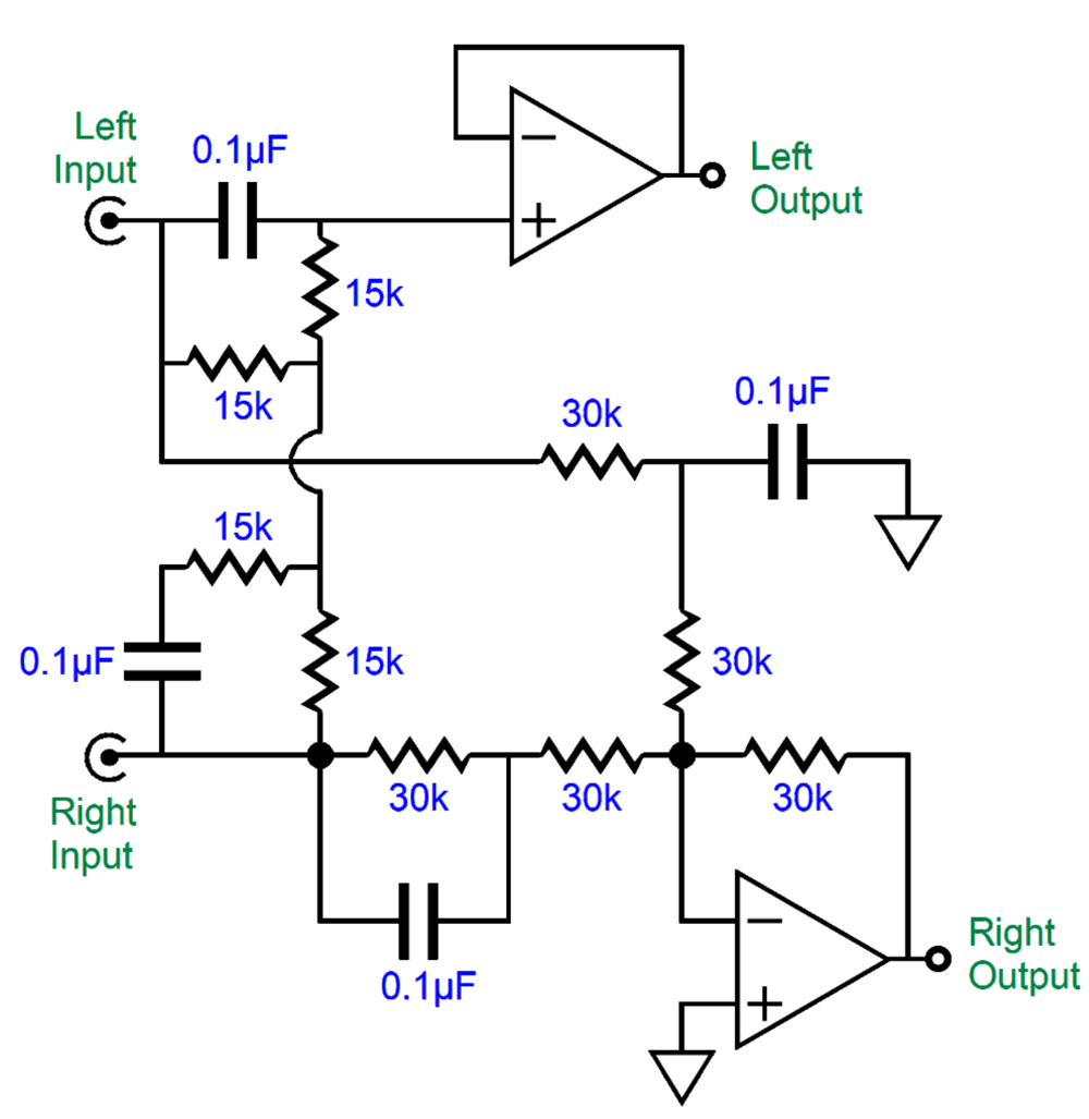
This circuit performs both the blending of bass signals below 106Hz and inverting the right channel's output. I effectively normalized all the resistor values to the 0.1µF capacitor value, as that capacitor value is easy to find in 1% tolerance. By the way, no monopolar power-supply rail splitting is going on here, so a bipolar power-supply is needed. Here is the bridge-amplifier setup with bipolar power-supply.
I know that this two-amplifier and three-driver arrangement is damn radical. In other words, it requires a lot of mind stretching.
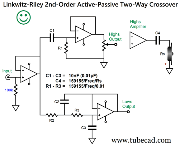
The one stipulation for making work that bothers me is the need to have all three drivers share the same SPL efficiency. You can easily find a fine fullrange driver and a good subwoofer driver, but finding the same SPL with watt at one meter is difficult. The best workaround is to drive the subwoofer with its own power amplifier, which would allow us to ditch the big and expensive crossover inductor, as an active crossover filter can be used instead. Since I want to avoid having to use a large-valued coupling capacitor for the subwoofer with a monopolar power supply, we can use a bridge amplifier arrangement. The fullranges will still need to be capacitor coupled, so we might as well make their coupling capacitor part of the crossover. Post 580 showed how active and passive 1st-order filters could be combined to create a 2nd-order Linkwitz-Riley crossover.
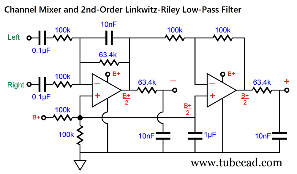
What is missing for our monitor-stand loudspeaker is a mixing circuit, so the subwoofer sees a mono signal, after it has passed through a 2nd-order 250Hz low-pass Linkwitz-Riley filter.
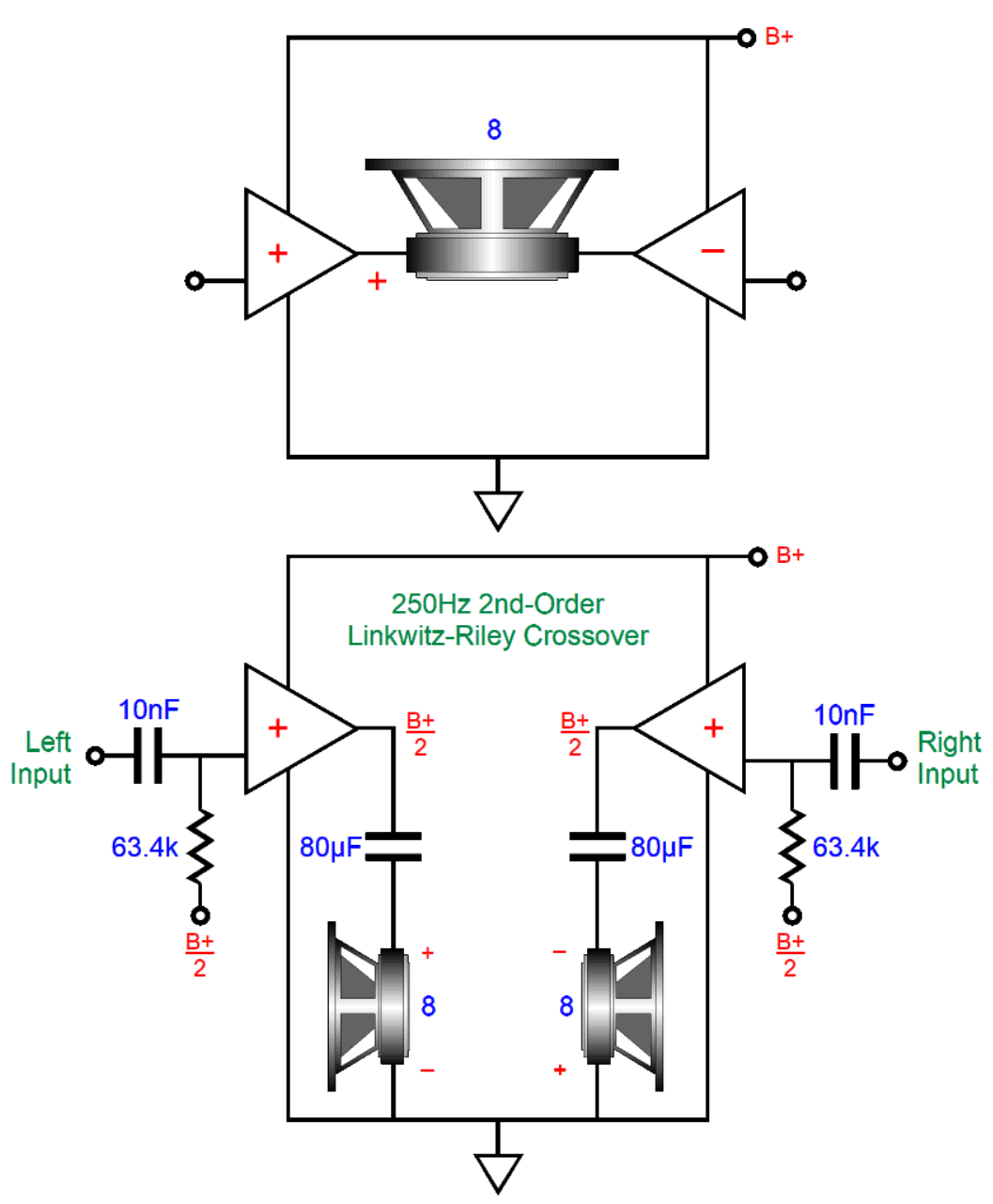
Yes, we are back to using a monopolar power supply. The OpAmp on the left functions both as a mixer and as a 1st-order low-pass filter with an inverting output signal. The OpAmp on the right functions as merely an inverting buffer, which delivers a non-inverting output signal. Both OpAmps drive passive low-pass filters that complete the required Linkwitz-Riley filter. We can alter the 100k resistor values up or down to adjust the sub's output to match the fullrange's SPL. Still assuming a monopolar power supply, the following shows the needed loudspeaker drivers and four power amplifiers arrangement.
Since the subwoofer gets four times more power than the fullrange drivers do, its SPL can be up to -6dB lower than the fullranges and still play as loudly. Note that the subwoofer's impedance is effectively halved by the bridge-amplifier topology, so an 8-ohm subwoofer should be used. Okay, I believe that I have squeezed as much as I can from this loudspeaker idea—for right now.
Third Alternative Use of Balanced Signals
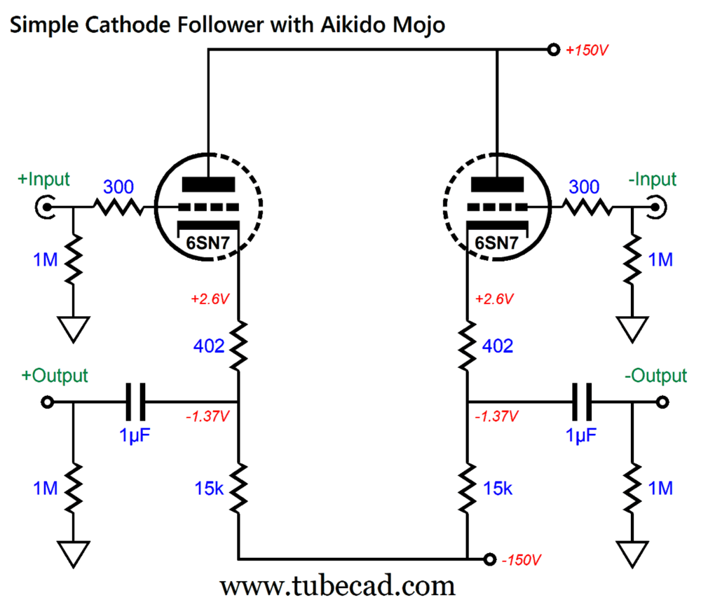
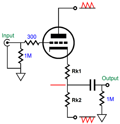
The simplest way to introduce some tube-based flavor is to buffer the DAC's balanced output signals with two cathode followers.
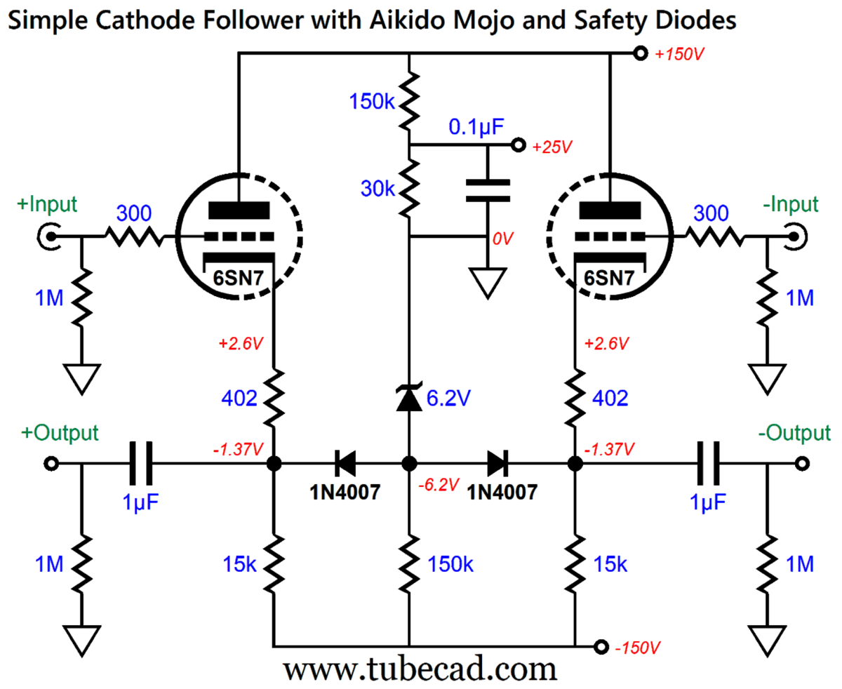
Each channel gets its pair of cathode followers. No input coupling capacitors are needed, and the two cathode resistors in series (402 and 15k) induce some Aikido mojo magic. Assuming that the high-voltage bipolar power supply presents equal and anti-phase ripple on its positive and negative rails, a profound PSRR enhancement results.
The formula for finding Rk1's value is simple. Rk1 = (Rk2 - rp)/(mu + 1) Where rp is the triode's plate resistance and mu is its amplification factor. This formula delivers the needed value for Rk1 so that the resistances above and below the output equal, so the bipolar power supply ripple nulls at the nexus, just a two-resistor voltage divider would. In addition, the 402-ohm cathode resistors shield the cathodes from dead shorts and capacitance, while the diminution of signal is trivial.
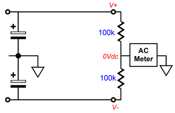
The problem we sometimes face is that the power transformer may not present a perfect center-tap. A mis-tapped center-tap creates an imbalance in ripple magnitude between power-supply rails. The test for a mis-tapped center-tap (or mis-matched power supply capacitors) is the following setup.
The workaround is to place either an inductor or a resistor in series with the transformer's center-tap and ground.
I have used 100-ohm to 1k resistors to good effect. The added resistor acts to undo the mis-tap and to function as an RC filter. Are we done? No, we are seldom done when it comes to audio circuits. Another problem we certainly face is that at turn-on, when the cathodes are at room temperature and not conducting, the 6SN7 grids are at ground potential, while its cathodes are at -150Vdc. Not good, as the huge voltage differential can damage the triodes due to cathode stripping, wherein the high-voltage differential causes chunks of the cathode material to rip away and fly up to the plate. The workaround uses a zener and two diodes.
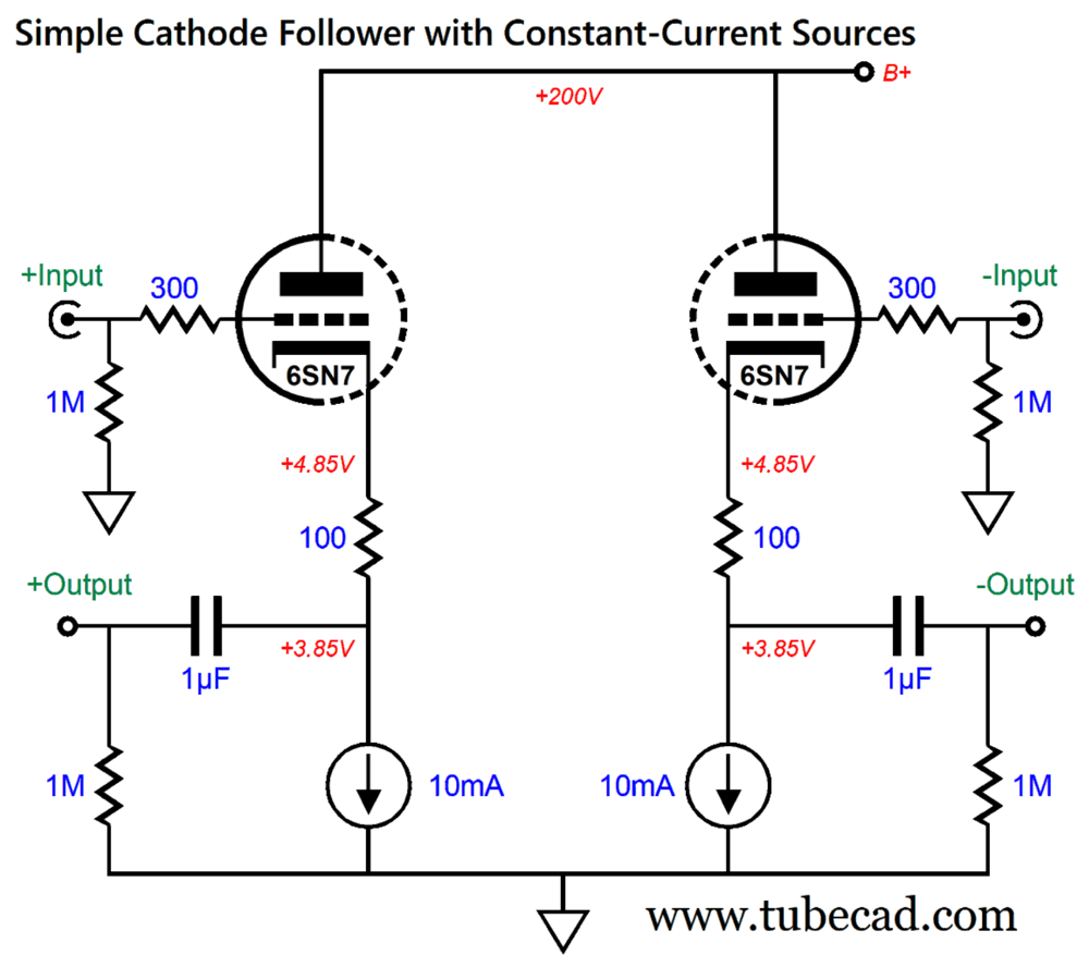
The diodes only become forward biased and conduct current when the outputs drop below 7V; during normal operation, they fall out of the circuit. The two-resistor voltage divider spanning from ground to the B+ voltage creates a positive-bias reference voltage for the heater power supply. In addition, it helps balance the two power-supply rail ripples. Some tube-loving folk, however, hate bipolar power supplies. Why? Some of them only use tube rectifiers, which the bipolar power supply make difficult, but not impossible. For others, they are philosophically opposed to negative power-supply rails. In other words, for some solder slingers any tube-based circuit that holds a high-voltage bipolar power supply is a nonstarter. For them the following circuit might meet with their approval.
Note that the B+ voltage has been increased to 200Vdc, which bought us a higher cathode voltage. We need the greater cathode voltage to contain the solid-state constant-current sources. Although we do expect the cathode followers to swing much more than 1Vpk, the constant-current source require a certain amount of overhead voltage within which to operate. Are we done? If the B+ voltage comes from a high-voltage regulator, we are. If the B+ voltage leaks any ripple, on the other hand, we can expect 1/mu of ripple to appear at the two outputs, where mu is the triode's amplification factor; 20, in the case of the 6SN7. As you might imagine, I have a workaround. In fact, I have been meaning to show the following circuit for years now.
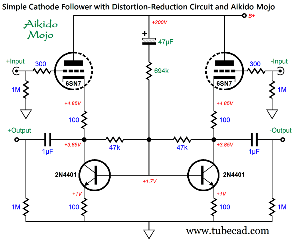
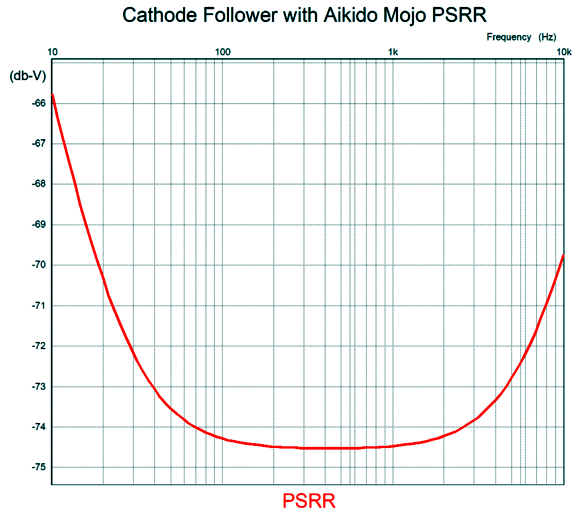
The constant-current sources have been replaced by two NPN transistors, which function as constant-current sources plus. The plus comes from their working to further balance the output signals, as the two 47k resistors define a two-resistor voltage divider whose center connection should see no AC signal, assuming perfect balance. An imbalance will create a correction signal and the transistors strive to restore balance. In addition, the 47µF capacitor and 694k resistor leak just enough power-supply noise to create a power-supply noise null at the outputs. How well does this circuit work? The PSRR in SPICE simulations was -72dB at 100Hz.
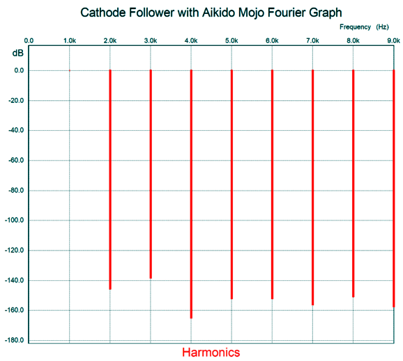
The THD was almost too embarrassingly low to mention. Here is the SPICE-generated Fourier graph for 1Vpk from each output at 1kHz, with the analysis performed on the differential signal, i.e. from output to output.
If a harmonic is -40dB below the fundamental, then that harmonic is 1% as large. In other words, the signal exhibits 1% distortion. If -60dB, then 0.01%; -80dB, 0.001%; -100dB, 0.0001%...
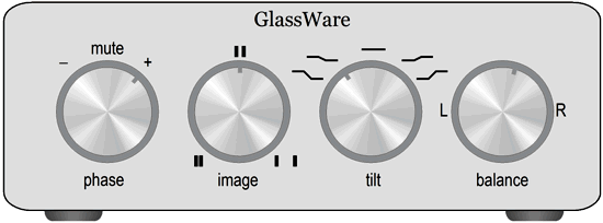
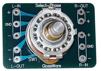
Returning to the topic of phase, we need only add a three-position rotary switch to any of these balanced cathode follower circuits, in between the DAC and the cathode followers, to easily flip the phase. We can then drive balanced and unbalanced power amplifiers. My assumption here is that we do not need volume attenuators, as the streaming music source allows volume controlling. If volume attenuation is needed, we can place it in between the DAC and the cathode follower grids.
Terje Isungset, a Norwegian jazz percussionist, was unknown to me, when Amazon music presented him as an artist I might like. I did like. In fact, his 2021 album, Glacial Poetry, has to be the coolest music I have heard. How so? All the instruments are made from frozen water. Here is what Bandcamp.com had to say:
By the second track, I was sold on the idea. His music is music, not a gimmick. The sound is warm and sweet, with deep bass notes and shimmering highs and excellent ambiance. I have listened to the album three times now, and I like it more with each listening.
Amazon Music offers, as does Qobuz, it in 24-bit, 48kHz.
//JRB
User Guides for GlassWare Software
For those of you who still have old computers running Windows XP (32-bit) or any other Windows 32-bit OS, I have setup the download availability of my old old standards: Tube CAD, SE Amp CAD, and Audio Gadgets. The downloads are at the GlassWare-Yahoo store and the price is only $9.95 for each program. http://glass-ware.stores.yahoo.net/adsoffromgla.html So many have asked that I had to do it. WARNING: THESE THREE PROGRAMS WILL NOT RUN UNDER VISTA 64-Bit or WINDOWS 7, 8, and 10 if the OS is not 32-bit or if the OS is 64-bit. I do plan on remaking all of these programs into 64-bit versions, but it will be a huge ordeal, as programming requires vast chunks of noise-free time, something very rare with children running about. Ideally, I would love to come out with versions that run on iPads and Android-OS tablets.
|
I know that some readers wish to avoid Patreon, so here is a PayPal donate button instead. Thanks. John Broskie
John Gives
Special Thanks to the Special 84 To all my patrons, all 84 of them, thank you all again. I want to especially thank
All of your support makes a big difference. I would love to arrive at the point where creating my posts was my top priority of the day, not something that I have to steal time from other obligations to do. The more support I get, the higher up these posts move up in deserving attention.
If you have been reading my posts, you know that my lifetime goal is reaching post number one thousand. I have 416 more to go. My second goal is to gather 100 patrons. I have 16 patrons to go. Help me get there.
Only $9.95
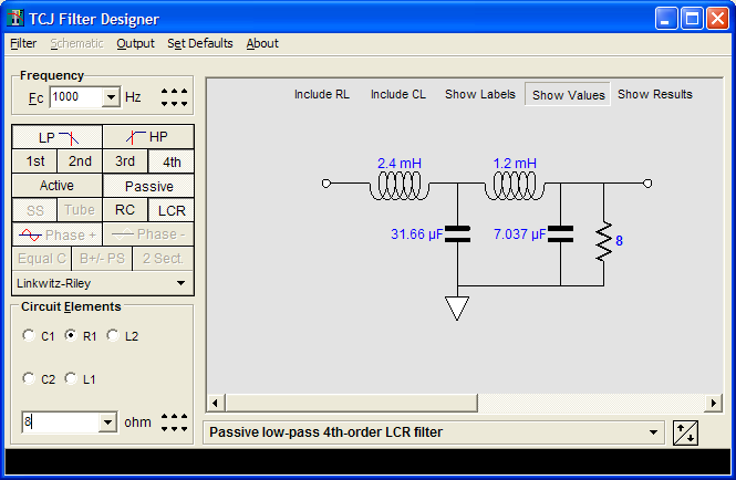
The Tube CAD Journal's first companion program, TCJ Filter Design lets you design a filter or crossover (passive, OpAmp or tube) without having to check out thick textbooks from the library and without having to breakout the scientific calculator. This program's goal is to provide a quick and easy display not only of the frequency response, but also of the resistor and capacitor values for a passive and active filters and crossovers. TCJ Filter Design is easy to use, but not lightweight, holding over 60 different filter topologies and up to four filter alignments: While the program's main concern is active filters, solid-state and tube, it also does passive filters. In fact, it can be used to calculate passive crossovers for use with speakers by entering 8 ohms as the terminating resistance. Click on the image below to see the full screen capture.
Tube crossovers are a major part of this program; both buffered and un-buffered tube based filters along with mono-polar and bipolar power supply topologies are covered. Available on a CD-ROM and a downloadable version (4 Megabytes). Download or CD ROM
|
|||


| www.tubecad.com Copyright © 1999-2023 GlassWare All Rights Reserved |