| John Broskie's Guide to Tube Circuit Analysis & Design |
08 Jully 2023 Post Number 584
Balanced for Balanced
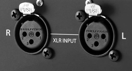
An obvious example would be driving power amplifiers with XLR balanced input jacks from a balanced line-stage amplifier. By the way, a power amplifier that accepts a balanced input signal does not have to offer a balanced output or even to employ a push-pull output stage. Yes, we could build a tube-based single-ended power amplifier with an XLR input jack.
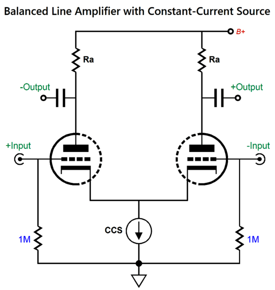
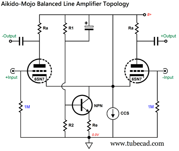
Vacuum tubes are so dang amazing that we can build a balanced line amplifier with just one low-mu, twin-triode tube, such as the 6H30, 6FQ7, 6SN7, 12AU7, 12BH7, 5687, ECC802, ECC99… (The 6BX7, sadly, is a poor choice, as its two triodes are usually poorly matched, as it wasn't designed for audio applications, unlike the 6SN7 and 12AX7.) As an example of a simple balanced line-stage amplifier, the following differential amplifier uses a constant-current source in place of a long-tail shared cathode resistor along with its required high-voltage negative power-supply rail.
The B+ voltage must be sufficiently high to develop a cathode voltage high enough to allow a solid-state constant-current source, such as the LM334, to operate. (One workaround is to add low-voltage negative power-supply rail, either -6.3Vdc or -12.6Vdc, to both terminate the constant-current source and power the heater element.) This arrangement provides low distortion and a high common-mode-rejection ratio (CMRR), but a poor PSRR. How poor? Very, as close to all of the power-supply noise will appear at both outputs, because the constant-current source ensures a constant-current voltage drop across the plate resistors at idle and a constant-current average voltage drop when amplifying signals.
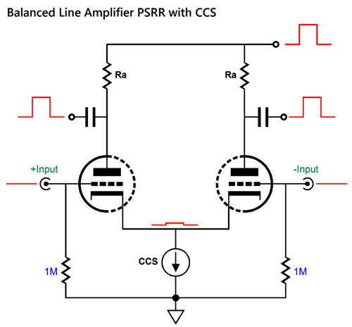
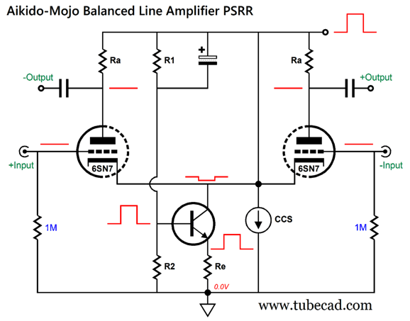
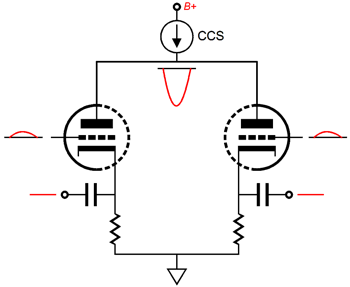
Here we see a single positive pulse forced on the B+ voltage, which induces an in-phase but tiny positive pulse upon the cathodes, equal to 1/mu, where mu is the triode's amplification factor. The pulse at the B+ connection leaks out the two outputs, making for a very poor PSRR. One workaround is to use either a tightly regulated or a passively highly filtered power supply. My workaround is to inject some Aikido mojo.
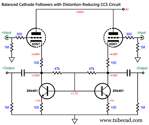
The added NPN transistor can be a low-voltage, low-wattage type, such as the 2N2222 or 2N4401. This transistor draws very little current, and its emitter resistor must be close to half the triode's plate resistor value. Resistor R1 is bypassed by a large-valued capacitor that relays close to 100% of the power-supply noise to the transistor's base, which the transistor will then impose upon its emitter resistor, thereby causing an anti-phase noise signal to appear at the cathodes, which in turn will prompt a lager anti-phase noise signal to appear at the plates, cancelling the power-supply noise.
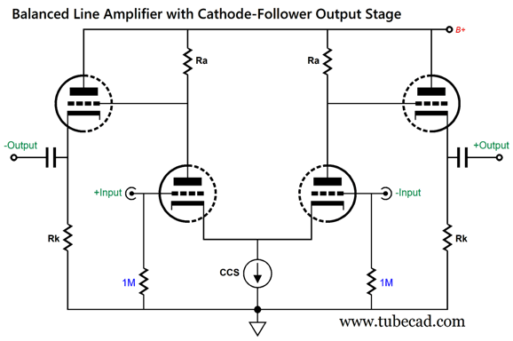
If the B+ voltage is entirely free of power-supply noise, then the transistor will merely function as an additional constant-current source that works in parallel with the existing constant-current source. Let's flesh out the design by adding two cathode followers, but without the Aikido-Mojo transistor.
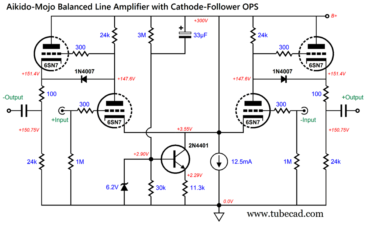
The cathode followers make the balanced line-stage amplifier far more load-independent by offering a low output impedance, but do nothing to improve the dismal PSRR. Okay, it's time for an actually buildable design example—with all the bells and whistles included, such as safety diodes and grid-stopper resistors.
The B+ voltage is a high 300Vdc; thus, the heater power supply must be referenced to +75Vdc, so as not exceed the cathode-to-heater voltage limit. Another workaround would be to use heater power supplies, one referenced +20Vdc for the bottom triodes, another to +170Vdc for the top triodes.
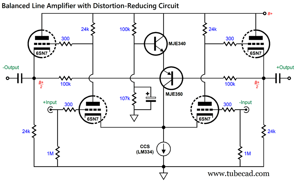
Balanced Line Amplifier with Distortion-Reducing Circuit
The two 47k resistors form a two-resistor voltage divider that expects to see no AC signal at its nexus with the transistor bases. If an AC signal is present, however, then the transistors will treat that AC voltage as signal to amplify and invert at their collectors. Here is an Aikido mojo variation on this topology, but with an added twist.
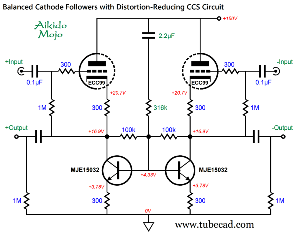
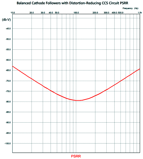
Note the change in vacuum tube and the lower B+ voltage. In addition, the two transistors see a much higher collector voltage; thus, the change in transistor types, going from small plastic encased transistors to robust TO-220 types. The assumption behind this variation is that big output voltage swings are expected. Note the inputs are capacitor coupled and that the grid-bias voltage is created by the voltage drop across the 300-ohm cathode resistors. How well how does this Aikido mojo modified circuit work at power-supply rejection?
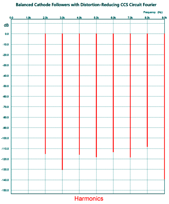
My aim was to hit the ripple frequency with the deepest null point. The SPICE-generated Fourier graph for 2Vpk-to-pk differential at 1kHz is truly interesting.
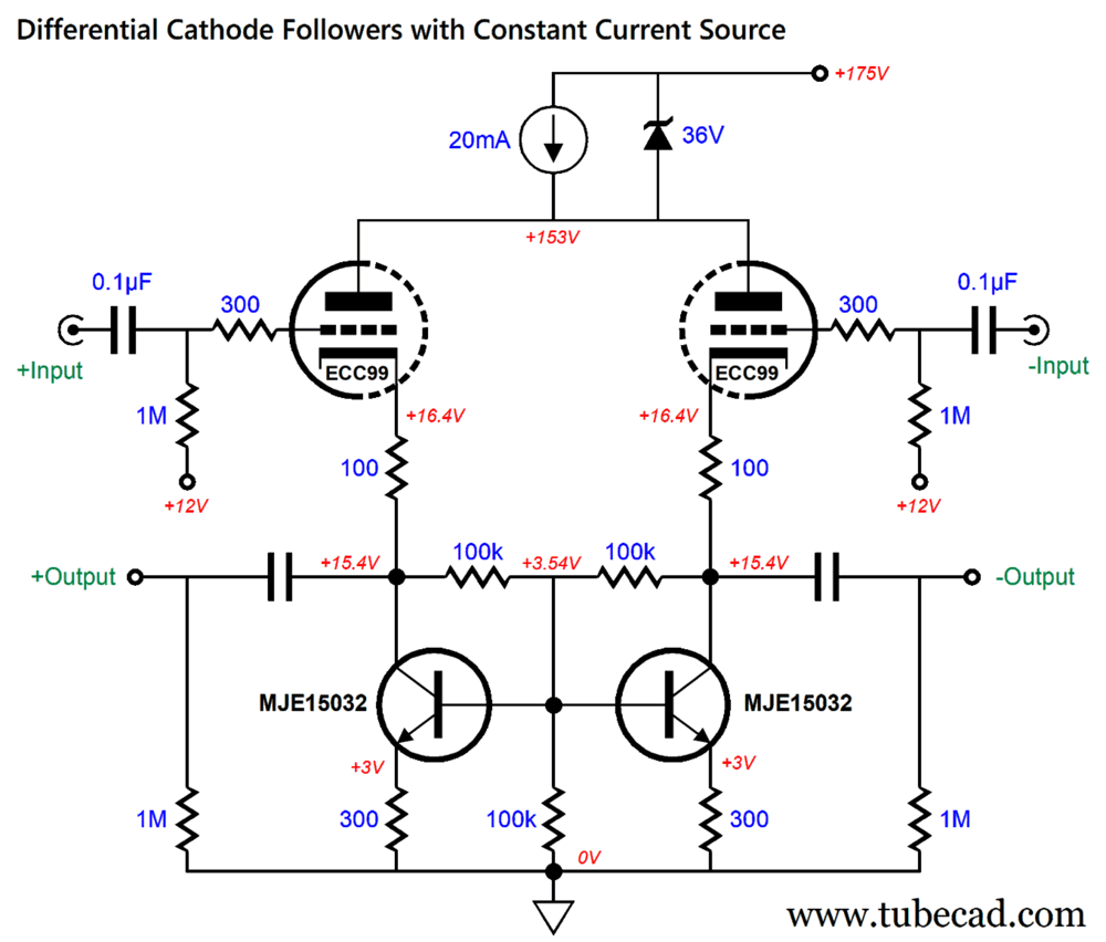
Note that, unlike most balanced audio circuits, the odd-ordered harmonics are reduced compared to the even-order harmonics. You might be thinking, "That's nice, John, but I really need a lower output impedance." Well, we can reduce the cathode resistors in value and use a fixed DC reference voltage to bias the grids, which lowers the output impedance. Indeed, we could also get extra fancy.
The 12Vdc bias voltage might come from a 12V heater power supply or from a two-resistor voltage divider that spans from ground to the B+ voltage. The critical part is the constant-current source at the top, as it not only sets the idle current but also bestows a few gifts. The first is a great PSRR, so much so that voltage regulation isn't required. Think about it: the constant-current source acts like an inductor with near infinite inductance. Second, its addition transforms the circuit into a phase splitter, as we can drive either input solely and still get a wonderfully balanced set of output signals. Third, it creates common-mode rejection (CMMR), as the two outputs won't pass signals common to both inputs. In other words, this is a differential cathode follower that rejects the same in-phase signal at both inputs. An example of a shared, but unwanted, in-phase signal, is hum from the signal source.
For more on this topology, see post 379. If this topology looks a bit familiar, it is probably due to you having seen it 13 years ago in post 191 , where I referred to it as a plate driven phase splitter. This topology only works with triodes, not transistors or MOSFETs, as a triode's plate is 1/mu as effective as its grid in controlling the flow of current through the cathode. For example, if both grids see a 1Vpk positive pulse and the plate sees a -30Vpk negative pulse at the same time, the cathodes will not budge, as the two countervailing pulses cancelled. The zener is there to protect the solid-state constant-current source from over voltages; for example, when someone plugs the wrong tube into the socket, thereby shorting plate connection to the heater power supply or the cathode resistor. Yes, high-voltage constant-current source can be built up with high-voltage transistors, but I like some extra safety. Which can be as little as single depletion-mode MOSFET or an LM317HV voltage regulator configured as a constant-current source or some discrete transistors. Well, we can add a similar sort of distortion-reduction circuit that we had used with the balanced cathode followers to the balanced differential line-stage amplifier.
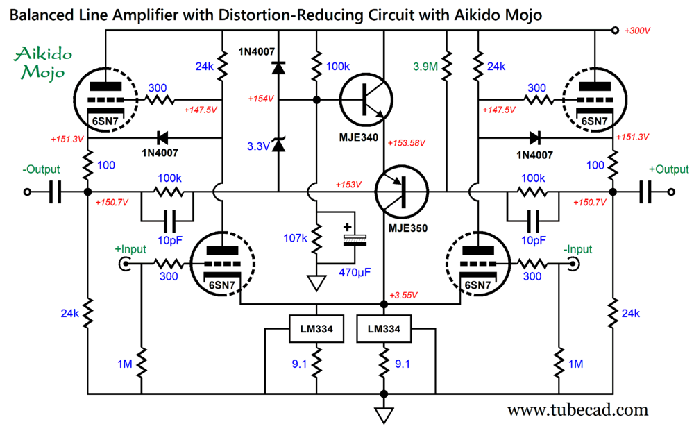
The two transistors from a bastode differential amplifier that sees and compares to different AC signals: through the bypassed 107k resistor, the NPN transistor's base sees the AC ground signal (in other words, zero AC signal); through the nexus of the two 100k resistors, the PNP transistor's base sees the distortion signal created by imperfectly balanced outputs. (If there is zero signal present, the two anti-phase output signals must be perfectly balanced.) The bastode circuit amplifies and inverts the distortion signal at the MJE350's collector, which terminates into the bridged cathodes and constant-current source. The result is an improved THD and PSRR, along with better balance. We can inject some additional Aikido mojo thus:
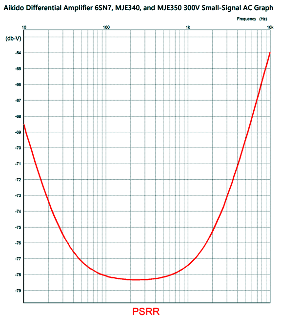
The added 3.9M resistor leaks a wee amount of power-supply noise into the PNP transistor's base to create a power-supply noise null at the output. The 470µF capacitor that shunts the 107k resistor may seem ridiculously too large in value, but SPICE simulations revealed that it is needed to ensure that the PSRR null extended below 100Hz. All the added diodes and the zener are there to protect the two transistors at turn-on and turn-off.
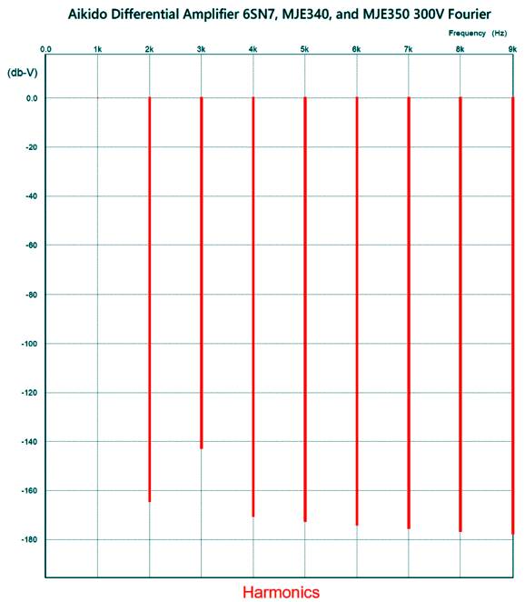
We see that at 100Hz the PSRR is an exemplary -78dB. SPICE simulations show an astoundingly low THD. Here is the graph for 1Vpk output at 1kHz from output to output.
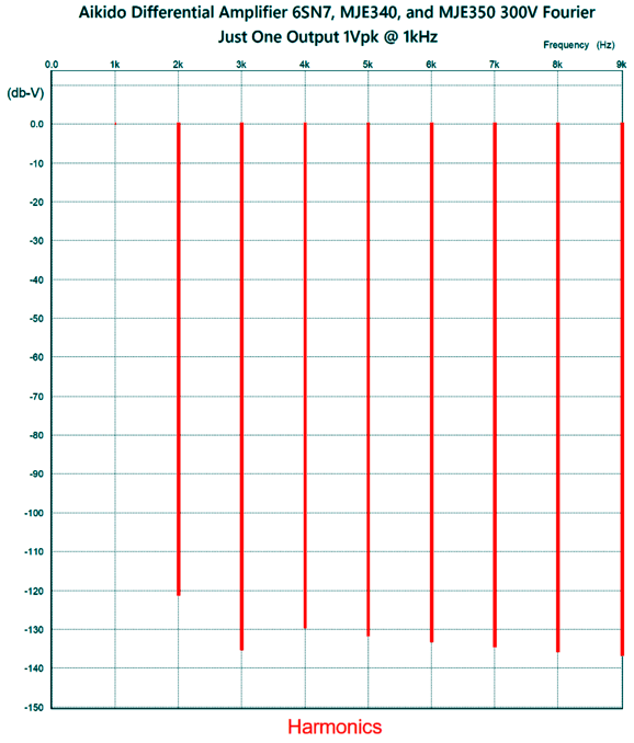
The distortion is quite low, but I wish the 3rd harmonic was further suppressed. Here is the Fourier graph for just one output at 1kHz. The input signal was doubled to get 1Vpk from each output (2Vpk differentially).
That's more like it, if and only if, you are using just one output at a time, say in an unbalanced system with a phase-selector switch. I must point out, however, that the 3rd harmonic is higher than it was in the differential-output evaluation. Indeed, all the harmonics are substantially higher.
Broskie Cathode Follower as Unbalancer
One of his requirements was the ability to drive 600-ohm loads. Later, I shared the circuit with a friend, who then used it to drive his 300-ohm Sennheiser headphones. I was convinced that 6DJ8-based BCF wouldn't be up to the task. He claimed that it was. I tried my own HD580 headphones and the BCF worked great. This makes sense as the BCF functions as an OTL output stage, with the top and bottom triodes delivering equal output current swings into the external load.
For the best CMRR, the two triodes must be tightly matched, so too the cathode resistor and all the resistors labeled R. I created the topology before I owned any SPICE programs, so I had to resort to reality and test equipment. Well, I recently evaluated the circuit's CMRR in SPICE simulations. I discovered that any attempt to tweak part values resulted in a worse CMRR. In addition, input coupling capacitor C2 must be used. The following design example exhibits low distortion and bandwidth out to 500kHz.
The circuit draws a little over 9mA. The PSRR is better than -30dB, with the 6DJ8. The CMRR is better than -54dB from 10Hz to 100kHz.
The 10µF output coupling capacitor may seem too large in value, but it was required to extend the CMRR deep into the low-frequencies. We can place a phase selector switch in front of the BCF circuit, allowing us to flip the phase as needed. The tube's heater power supply should be referenced to 50Vdc, which will split the difference between top and bottom cathode voltages. The 6DJ8 works well with the relatively low B+ voltage, as would a 5687 or ECC99. With a 6SN7, I would raise the B+ voltage to 240Vdc to 300Vdc.
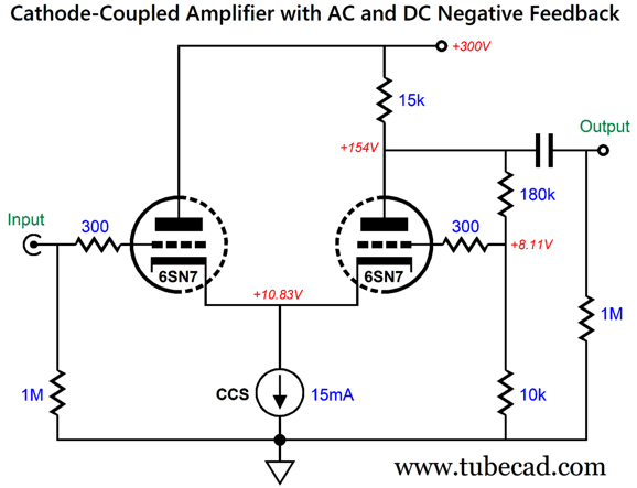
Aikido-Mojo Cathode-Coupled Amplifier
Yes, some AC negative feedback is employed as well, but not that much—at least not with this 6SN7-based design example, as the 180k and 10 feedback resistors imply a gain of 19, but the 6SN7 cannot, with mu of only 20, deliver that much gain in this circuit. Note the 15mA constant-current source. The input triode on the left draws about 5mA, while the output triode on the right draws closer to 10mA. The result is that both triodes dissipate about the same amount of heat, around 1.5W. We can greatly improve the amplifier's PSRR by adding some Aikido mojo.
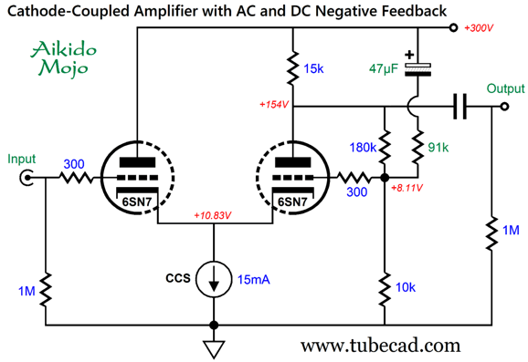
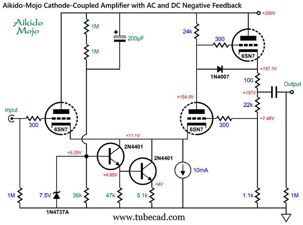
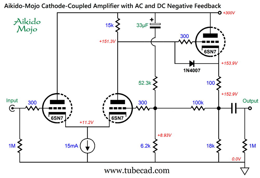
The 47µF capacitor and 91k resistor leak enough power-supply noise to force a deep power-supply-noise null at the output. In SPICE simulations, this circuit yielded a lovely single-ended cascade of harmonics in Fourier tests. With the Aikido-mojo parts in place, the PSRR comes in at -47dB at 100Hz; without, only -4dB. If a much low output impedance is needed, we can add a cathode-follower output stage, whose cathode resistor(s) can serve as the negative feedback loop for the cathode-coupled amplifier.
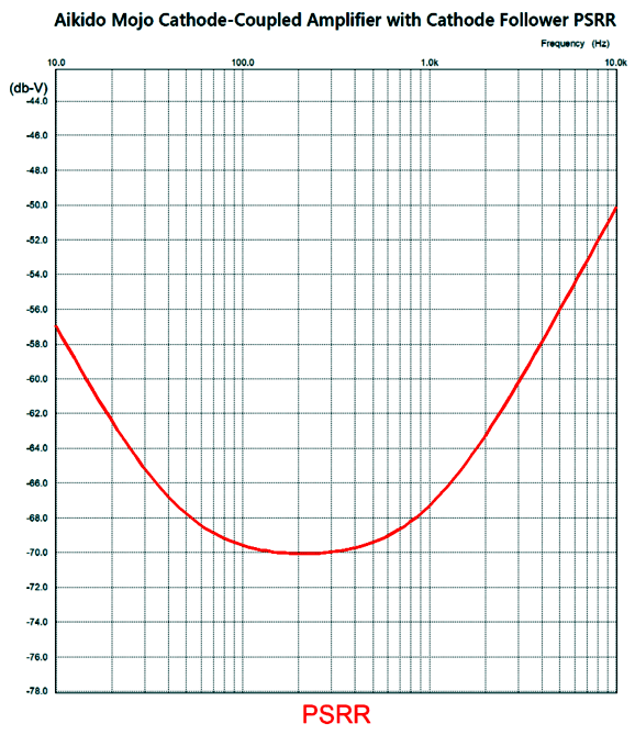
The two low-voltage transistors add the needed Aikido mojo. Once again, the zener and diode are there to protect the cathode follower triode and the transistors at turn-on and turn-off. How well does Aikido mojo work?
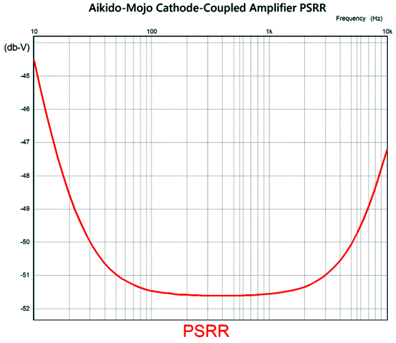
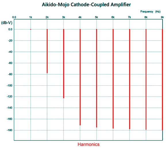
At the critical 100Hz and 120Hz frequencies, the PSRR approaches -70dB. This is dang fine for a tube-based circuit, as we can further improve the PSRR by adding an RC filter or high-voltage regulator to the B+ voltage. With 1Vpk out at 1kHz, the distortion is wonderfully low in SPICE-generated Fourier analyses.
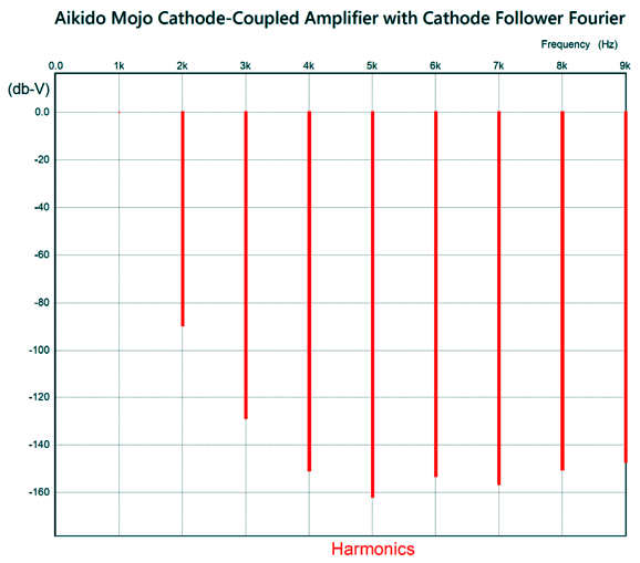
At -80dB, the distortion is only 0.01%. Note the single-ended cascade of harmonics. Lovely. Here is variation that uses what I call a cynosure resistor.
What I like about this circuit is that it could have been created in 1963, not 2023. Here is the SPICE-generated PSRR graph.
Its Fourier graph looks sweet.
Okay, I fear I am entering the need-to-prune zone here. Returning to my observation that this circuit designs could have been created in 1963, the 15mA solid-state constant-current source might seem to preclude that possibility. Texas Instruments introduced the first silicon transistors in 1954, beginning silicon's dominance as the preferred semiconductor material. Nonetheless, germanium-based can be used to build constant-current sources. In the early 1960s, transistorized radios were being sold. Indeed in 1963, Donald Charles Scouten developed his quasi-complementary symmetry transistor power amplifier design. Transistors are older than I am, and I am old.
Music Recommendation: Blues Albums
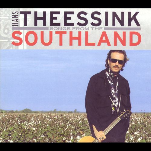
Soon, I was flooded with emails thanking me for making the recommendation, as the CD proved the best-sounding in their collection; in addition, they pleaded for more recommendations. If you are like me, you have a few special tracks of music at the ready whenever you evaluate any change in your audio system. Well, just about any track on Guy's Blue Singer works for me. Recently, my friend, Glenn, and I have sought equally fine sounding albums. No easy task. One contender is from Hans Theessink, Songs from the Southland.
With excellent sonics and performance, this album is one to keep at hand when testing a new circuit with my ears. Like Buddy Guy's Blue Singer, this album amazes in spite of its mere 16-bit, 44.1kHz format. Another challenger is from Tim Williams' 1969 album, Blues Full Circle.
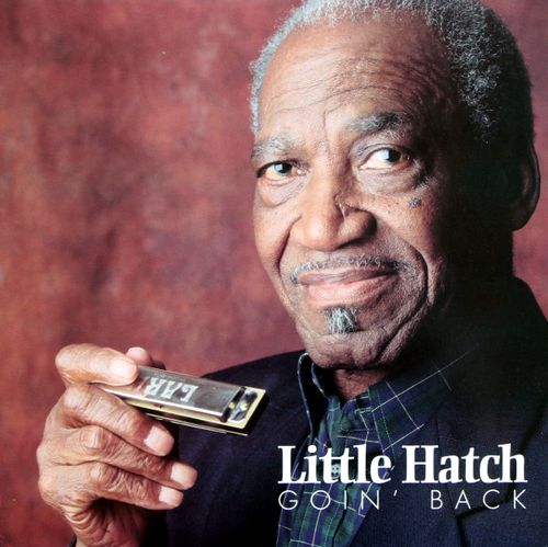
I listened to the 24-bit, 96kHz format offered by Amazon Music, but I see that Qobuz offers it in 192kHz! Williams was unknown to me, but I found an excellent piece of background on him and his music at therockasteria.blogspot.com. In my quest, I discovered Little Hatch, whose 2003 album, Rock With Me Baby, certainly rocked me.
In spite of its modest 16-bit and 44.1kHz recording, it sounds great. I am listening to his 1998 album, Going' Back, as I write this. It, too, sounds great.
Cheer yourself up, listen to some blues.
//JRB
Did you enjoy my post? Do you want to see me make it to post 1,000? If so, think about supporting me at Patreon.
User Guides for GlassWare Software
For those of you who still have old computers running Windows XP (32-bit) or any other Windows 32-bit OS, I have setup the download availability of my old old standards: Tube CAD, SE Amp CAD, and Audio Gadgets. The downloads are at the GlassWare-Yahoo store and the price is only $9.95 for each program. http://glass-ware.stores.yahoo.net/adsoffromgla.html So many have asked that I had to do it. WARNING: THESE THREE PROGRAMS WILL NOT RUN UNDER VISTA 64-Bit or WINDOWS 7, 8, and 10 if the OS is not 32-bit or if it is a 64-bit OS. I do plan on remaking all of these programs into 64-bit versions, but it will be a huge ordeal, as programming requires vast chunks of noise-free time, something very rare with children running about. Ideally, I would love to come out with versions that run on iPads and Android-OS tablets.
|
I know that some readers wish to avoid Patreon, so here is a PayPal button instead. Thanks.
John Broskie
John Gives
Special Thanks to the Special 85 To all my patrons, all 85 of them, thank you all again. I want to especially thank
All of your support makes a big difference. I would love to arrive at the point where creating my posts was my top priority of the day, not something that I have to steal time from other obligations to do. The more support I get, the higher up these posts move up in deserving attention.
If you have been reading my posts, you know that my lifetime goal is reaching post number one thousand. I have 419 more to go. My second goal was to gather 1,000 patrons. Well, that no longer seems possible to me, so I will shoot for a mighty 100 instead. Thus, I have just 18 patrons to go. Help me get there. Thanks.
Only $12.95 TCJ My-Stock DB
Version 2 Improvements *User definable Download for www.glass-ware.com
|
|||


%20Circuit.png)
%20Circuit%20Design%20Example.png)
%20Circuit%20CMRR%20Test.png)


| www.tubecad.com Copyright © 1999-2023 GlassWare All Rights Reserved |