| John Broskie's Guide to Tube Circuit Analysis & Design |
28 October 2023 Post Number 589
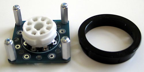
Universal PCB with Sockets Back In Stock
Visit my GlassWare store to check out and to buy.
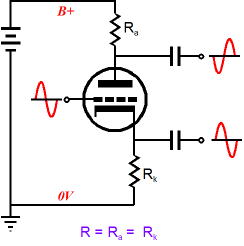
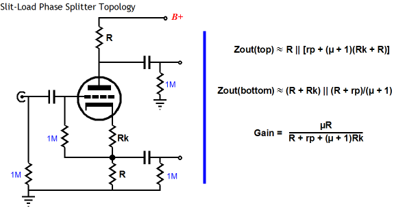
Split-Load Phase Splitter as OPS The first complaint, unity-gain outputs, only has merit if you desire gain; in fact, if you think about it, the split-load phase splitter does offer a gain of 2, as the differential of both outputs equals twice the input signal magnitude. The second criticism, mismatched output impedances, only makes sense when the phase splitter is driving unbalanced load impedances, which push-pull output stages simply aren't. A push-pull output stage that held two output tubes, a KT88 and 2A3, would make little sense—no matter how arresting the appearance.
My grumbles about the topology differ, as I bemoan the potential problems of limited output voltage swings and dissimilar PSRR figures from its two outputs. Of course, we do not always want or need the big output voltage swings; and if the power supply is truly noise-free, dissimilar PSRR is not a problem as there would be no power-supply noise to reject.
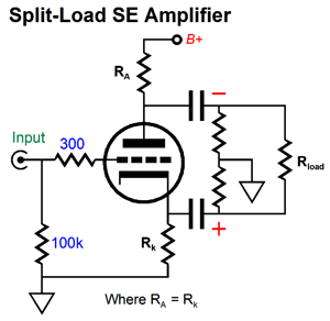
Indeed, in some circuits, the inverting output's near zero PSRR actually proves to be a feature, not a bug. What about when the split-load phase splitter does not cascade into another circuit, but connects to the external load? Things get interesting, which is why I am writing this post. Many of my posts have detailed how the split-load phase splitter can be used as an output stage, which troubles some. Why? They fear unbalanced output impedances. There is none; there can't be—such is the glory of true balanced operation that makes no connection to ground. An external load, such as a headphone driver or transformer primary, attached across the two outputs sees an equal low-impedance, not a high or dissimilar impedance.
In fact, if we replace the triode with a MOSFET or transistor, the output impedance can be staggeringly low: roughly, twice the inverse of the transconductance. For example, a MOSFET that offers 10A/V of transconductance presents an output impedance of 0.2 ohms.
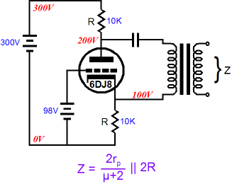
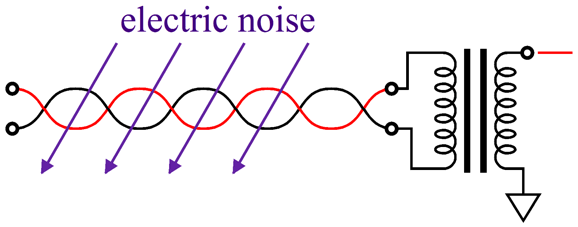
Even a 6DJ8 triode presents an output impedance below 200 ohms in this configuration. When configured with a bridging load, however, the issue of PSRR departs from conventional understanding, as convention references all noise to ground. The bridging load does not, however, attach to ground. In this situation, noise is measured differentially from the two outputs, not ground. In fact, both outputs can present a truly obscene amount of noise relative to ground, with no ill effect, as long as the amount of noise is equal and in-phase between outputs. Here is an example of how this is possible: imagine a headphone driver whose two terminals each attach to 100Vac. No smoke, no thundering sound. Why not? No differential voltage difference, no effect. As far as the voicecoil is concerned, nothing special is going on at its delicate voicecoil. Even when the external load is ground referenced (and therefore not truly balanced), a common, in-phase, equal in amplitude noise may not prove troublesome, as long as the circuit driven exhibits a good amount of common-mode rejection (CMRR). CMRR makes noise-free operation possible in spite of extremely noisy environments.
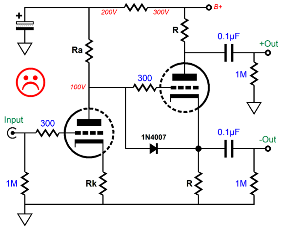
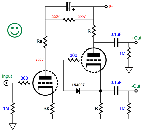
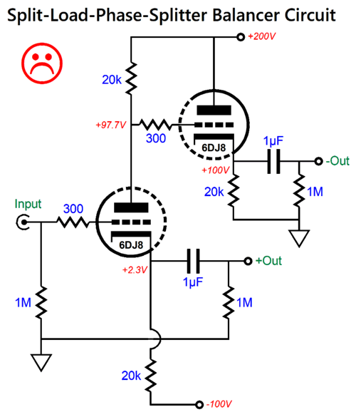
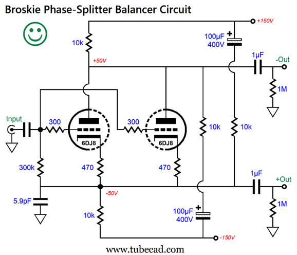
Ensuring equal power-supply noise at each output of the split-load phase splitter, however, requires some care and much thought. For example, the following circuit seemingly looks good, but fails.
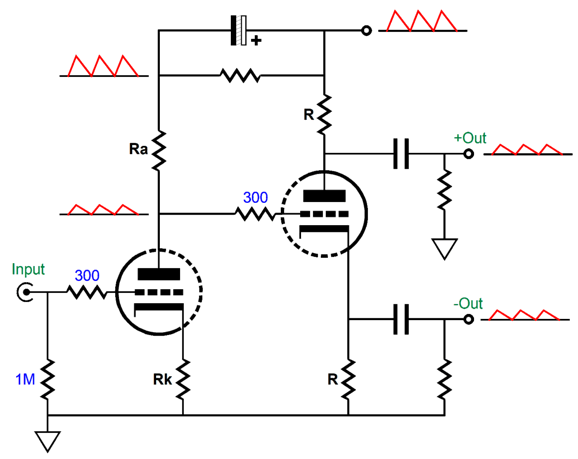
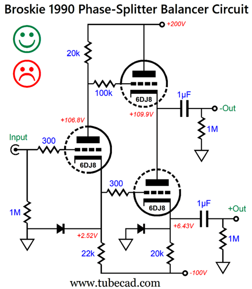
Whatever power-supply noise is riding on the B+ voltage will pretty much leak out of the non-inverting output, as that output delivers a very poor PSRR, while the inverting output delivers an excellent PSRR figure. If we just perform a small rearrangement of the existing parts, we split the power-supply noise at each output, which the following circuit's CMRR should eliminate.
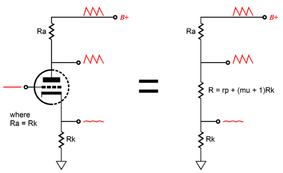
The input triode's effective plate impedance equals its plate resistor, so the two define a 50% two-resistor voltage divider. The inverting output relays this halved power-supply noise at its output, while the anti-phase current flow counters the power-supply noise at its plate, cutting it in half, thereby delivering the same halved power-supply noise at the non-inverting output.
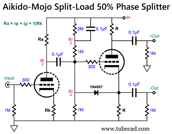
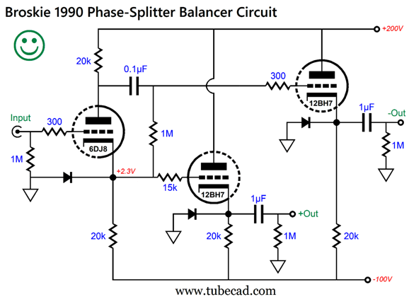
The following variation delivers more gain (due to the larger in value plate resistor for the input triode) and forgoes the use of the large-valued electrolytic capacitor.
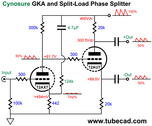
This topology ensures an equal 50% power-supply noise leak. Note how even the two 1M resistors in series, along with the bypassed 2M resistor, ensure a 50% division of the power-supply noise. Over the decades, I have shown many sneaky ways to balance the PSRR on the split-load phase splitter's outputs. In post 536, we see how the balance is forced by the addition of a "cynosure" resistor.
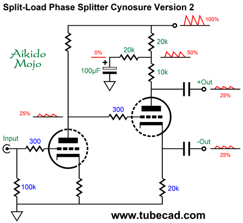
The 124k resistor injects enough power-supply noise to force an equal and in-phase power-supply noise leak from both phase splitter outputs. Another cynosure variation places the added resistor at the top.
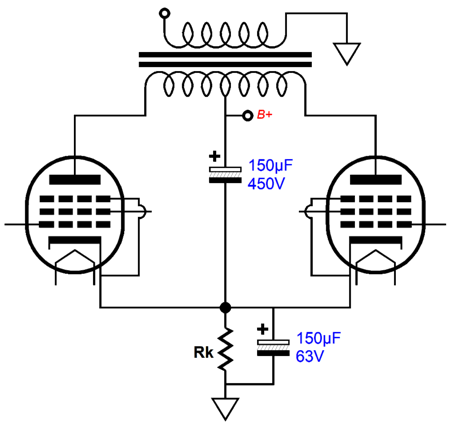
The two 20k resistors at the top are effectively in parallel with each other, making a combined resistance of 10k, which added to the 10k plate resistor equals a 20k load, thereby matching the 20k cathode resistor. One trick I like to employ with the pair of push-pull output tubes is to use two cathode-resistor-bypass capacitors. I set the ratio between capacitances to equal amount of power-supply noise presented by the split-load phase splitter's outputs. If the amount equals 50%, then the one-to-one ratio is used:
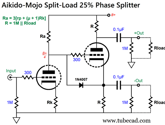
Now, the output tube cathodes see the same halved power-supply noise as the grids do. If 25% of the power-supply noise appears at both of the phase splitter's outputs, then the bottom capacitor needs to be three times larger in value than the top capacitor; with a 33% leak, twice as large. If the grids and cathodes see the same signal, that signal is largely ignored by the pentode or triode. The output transformer remains the primary CMRR device, but the second bypass capacitor helps when the output tubes leave their window of class-A operation. (When the class-A window of conduction is exceeded, one output tube turns off completely, so the output transformer can no longer work its CMRR magic, as both ends of the primary no longer see the same amount of power-supply noise.) In addition, the added cathode power-supply noise helps prevent the actual audio signal inter-modulating with the noise, as both grid and cathode are equally noise-filled. Moreover, no extra parts are actually needed, as the main power-supply reservoir capacitor's negative termination need only be changed from ground to the top of the cathode resistor. Of course, if multiple pairs of output tubes are used, each pair should get its own shared cathode resistor and two capacitors. In this setup, the output tube cathodes see the same halved power-supply noise as the grids do in a power amplifier, as the split-load phase splitter cathode and plate resistors are so vastly lower in resistance than the grid resistors driven that the grid resistors on the other side of the coupling capacitors can be ignored, being between 300k to 1M in resistance. What if an external load presents a much lower resistance, say 10k to 47k? In short, this topology now fails to provide the equal 50% power-supply noise leak. Effectively, the split-load phase splitter has now become an output stage, as the external load resistances can no longer be ignored. Here is my workaround variation. The topology remains the same, but the selection of part values changes.
Assuming that Rload equals 47k, resistors labeled R must equal 44.9k. In order to see how this arrangement works, imagine that the split-load phase splitter is missing its triode. Sans triode, the non-inverting phase splitter's output will naturally halve the power-supply noise at the B+ voltage connection, as the plate resistor and the load resistance equal each other. Now, imagine the triode in place. The input stage delivers 25% of the power-supply noise to the phase splitter's input, which in turn will leak from its inverting output and prompt enough anti-phase current flow to halve the pre-existing 50% of power-supply noise, leaving 25%. Yes, math is like magic, except that it works. (What a perfect statement to emblazon upon a T-shirt or coffee mug.) Note that the formula, R = 1M || Rload, only works in this special case where the input stage quarters the B+ voltage noise at its output. What if the input stage only thirds the noise? A different formula is needed.
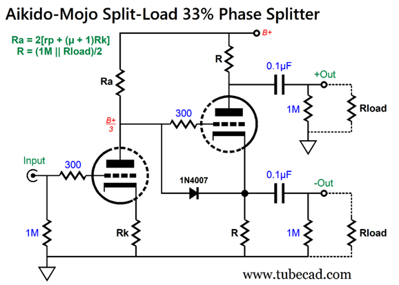
The formula now reads: R = (1M || Rload)/2. The result is that the non-inverting output leaks 66.6% (2/3) of the power-supply noise without the triode; 33.3%, with the triode.
In post 533, I revealed my encounter three decades ago with a high-end audio company who wanted my help in explaining why their brilliant tube circuit failed to work in practice. Their circuit worked great when attached to an oscilloscope, but failed hard when driving an actual solid-state power amplifier.
The goal was to turn an existing stereo power amplifier into a mono bridge amplifier, which would deliver up to four times the output power. The huge problem here is that the split-load phase splitter sees radically different loads at its two outputs: a big no-no. If the external load presents any capacitance, the high-frequency response at the non-inverting output remains flat, while the inverting output sees a high-frequency boost. If the external load presents a low resistance, the inverting output delivers gain, breaking the balance with the non-inverting output. A mess. (Read post 533 to get all the gory details of dealing with a high-end audio company with more ambition, money, and style than common sense.) One of the alternative phase-splitter circuits I devised back then, as an alternative to their failed circuit, was the following.
I rediscovered my old design recently, while looking through old papers of mine. I created it before I owned a SPICE program (before Windows 3.1 in fact). The other day, I ran this circuit through several SPICE simulations and was impressed with how well it worked. The balance was fairly good and the distortion low. It, however, suffers from the same problem of dealing with external load capacitance. A better approach is the following:
Three current paths exist between the negative power-supply rail and the positive rail, not two as in the previous version. Note the 15k grid-stopper resistor for the bottom 12BH7 triode, which equalizes the high-frequency bandwidths. (The assumption here is that the input signal does not exceed 3Vpk, as the diode at the input will become forward biased with greater input voltage swings. The diodes are needed to protect the triodes at turn-on.) The next variation is my favorite.
Note the high-voltage bipolar power supply with symmetrical rail voltages, which eases the creation of the high-voltage bipolar power supply. As long as the ripples on both power-supply rails are equal in magnitude and opposite in phase, a super deep power-supply-noise null obtains. The high-frequency bandwidth extends beyond 1MHz. The 5.9pF equalizes the high-frequency extension between the two outputs. Yes, this circuit is a bit complicated, and it requires three coupling capacitors, but it delivers the goods. This circuit allows us to turn a stereo power amplifier into a mono bridge amplifier.
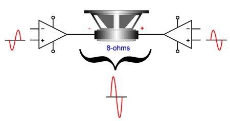
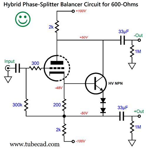
A quick review of the bridge-amplifier concept is in order. Tube-based OTL power amplifiers are grossly current-limited, but excel at big output voltage swings. Solid-state power amplifiers are voltage-limited, but excel at huge current swings. Thus, two bridged tube-based OTL amplifiers make no sense, as this arrangement only exacerbates the OTL's weak-current-delivery problem, as an 8-ohm loudspeaker appears as a 4-ohm load to the bridge amplifier. (Placing the two OTL amplifiers in parallel, however, would vastly increase the output power, roughly fourfold.) In contrast, the solid-state bridge amplifier topology exploits the high current-delivery potential of transistors and MOSFETs. In short, a solid-state bridge amplifier will deliver twice the wattage into an 8-ohm loudspeaker that a single amplifier will deliver into a 4-ohm load. For example, if a single amplifier delivers 100W into an 8-ohm load and 180W into a 4-ohm load, two of these amplifiers arranged in a bridge amplifier will deliver 360W into an 8-ohm load. Here is a hybrid design that counts as an output stage.
This a super-triode inspired design, as the triode draws a nearly constant current, so the transistor does the heavy lifting, but controlled by the triode.
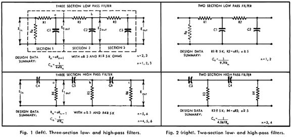
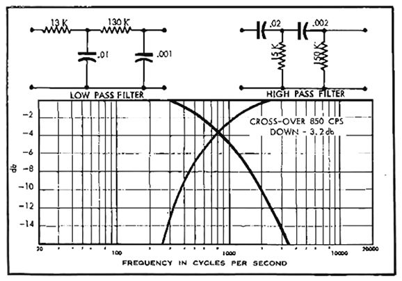
While perusing an old copy of Audio magazine, I found an article by Charles W. Harrison, titled "RC Filter Design for High-Impedance Crossover Networks," starting on page 34 of the November 1958 issue. Harrison provides formulas for both 2nd-order and 3rd-order passive crossovers that use only capacitors and resistors (no inductors).
The article is filled with math, math that seeks to create a pair crossover filters whose outputs are down -3dB at the crossover frequency. Sadly, being down -3dB only delivers a flat frequency response with 1st-order and 3rd-order crossovers, not 2nd-order.
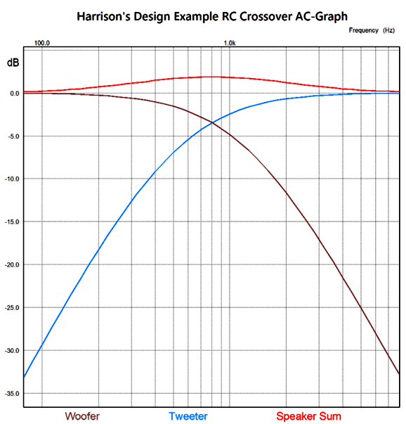
I ran Harrison's 2nd-order design example through some SPICE simulations and witnessed the expected bump at the crossover frequency.
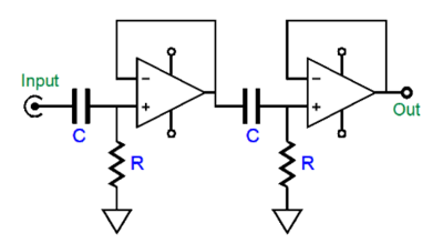
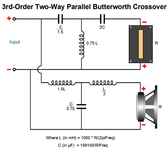
The hump peaks at about 1.9dB. (By the way, the actual crossover frequency appears closer to 800Hz than 850Hz.) To get a flat frequency response from a 2nd-order crossover requires that both drivers output be -6dB down at the crossover frequency, which is what the Linkwitz-Riley 2nd-order alignment delivers. How do we make a Linkwitz-Riley 2nd-order crossover passively with just capacitors and resistors? If we place a unity-gain buffer in between RC filter sections, the math follows the textbook: R = 159155/C/Freq C = 159155/R/Freq where C is in µF. We start by specifying the capacitor C, as far fewer readily available capacitor values exist compared to resistors.
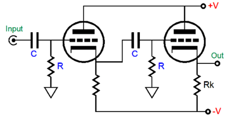
Each RC filter imposes a -3dB output at the crossover frequency, which combines to -6dB. Here is the same idea but with triodes.
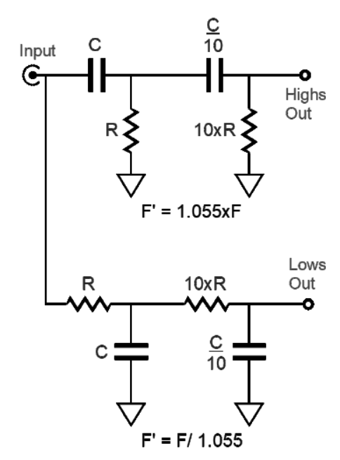
Of course, both these examples are effectively active, not passive designs, so a better label might be "feedback-free active filters." Pure-passive is possible, however, with some tweaking. My tweak is to take the crossover frequency and multiply by 1.055 for the high-pass filter, and divide the crossover frequency by 1.055 for the low-pass filter.
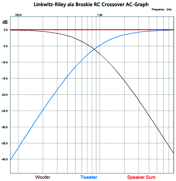
For example, with a crossover frequency of 1KHz, we would use 1055Hz for the calculation on the high-pass filter and 948Hz for the low-pass filter. Since both filters move away from the specified crossover frequency, more attenuation accrues at the crossover frequency. Here is the SPICE-generated graph for my tweak.
By the way, 2nd-order filters require flipping the phase on the tweeter to avoid a deep suck-out. In addition, this all-passive 2nd-order filter assumes a high-impedance input impedance of the following circuit—and a low input output impedance from the preceding circuit. If the filters terminate into a low-impedance or the driving circuit presents too high an output impedance, the filtering fails to deliver the desired output. A workaround would be to follow the filters with buffer stages. (This assumes that the signal source offer a low output impedance, such as line-stage amplifier or DAC or tuner… Placing a volume potentiometer in between the signal source and the filter will not work.)
Problem? What problem? Before spelling that problem out, let's just step back and consider why so many high-end loudspeaker hold obscenely complex passive crossovers, crossovers that bear little resemblance to textbook crossover circuits, looking more like a jigsaw puzzle forced together with a mallet by a blind man. Why the overly complicated and unfathomable crossovers? A flat frequency response—at any cost, such as expense or forgoing a flat impedance plot or a phase response. This all-too-common situation reminds me of an old joke, which I first heard being described as a quintessential Southern joke.
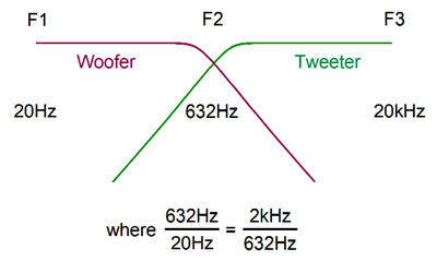
Returning to loudspeakers with misshapen passive crossovers, if woofers and tweeters were perfect, we would see simple, textbook passive crossovers used. Of course, the harsh reality is that all drivers fall short of perfection. Indeed, if a perfect loudspeaker driver existed, no crossover would be need, as it would cover the entire range of audio frequencies from 20Hz to 20kHz by itself. (Imagine a SciFi force field shaped as floor-to-ceiling cylinder that that expanded out and in, tracing the power amplifier's output perfectly, as only a massless driver could, offering a frequency response flat from 1Hz to 100kHz.) Alas, even fullrange electrostatic speaker panels fall short due to their beaming of high frequencies. In contrast, the headphone's single driver can deliver a compelling approximation to perfection. (I have heard single-driver, fullrange loudspeakers sound amazing, in terms of stereo imaging and midrange clarity, not in terms of low- and high-frequency extension.) I long to build a loudspeaker that holds two identical fullrange drivers, using only a 1st-order crossover at 600Hz. The idea behind the speaker being that the crossover frequency is the roughly geometric center frequency of the audio bandwidth. Moreover, 600Hz is low enough to prevent severe interference and lobing effects due to the spacing between drivers. (At 600Hz, the wavelength is about 23 inches.)
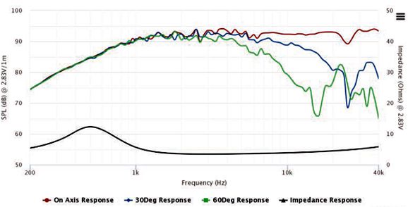
In addition, the 1st-order crossover delivers a phase-flat summation of driver outputs. Since the fullrange drivers share the exact same frequency and phase response, the two should perform as well as a single driver—but better, as the crossover will lower the amount of frequency-modulation distortion (FMD), the result of the Doppler effect producing frequency modulation when a loudspeaker driver reproduces simultaneously a low frequency and a high frequency. As the driver moves forward while reproducing a low frequency, the high frequency rises in frequency as its waves are bunched together, but when the cone moves backward, the high-frequency waves become stretched, reducing their frequency. Both electrostatic loudspeaker and headphones see very small diaphragm movement and, thus, create little FMD. In contrast, a 6-inch fullrange will make big cone movements as it reproduces low-frequency musical content. The two-way fullrange driver setup sidesteps this problem. While fullrange drivers are relatively rare, woofers and tweeters are common. Each has been optimally designed to cover its limited frequency range; thus, we get big, heavy woofers and small, light tweeters. This is seemingly the perfect solution, but we run into a snag. The tweeter's resonant frequency falls in the midrange, as low as 250Hz and as high as 2kHz, but usually centered at 600Hz, give or take a 100Hz. A driver's resonant frequency acts like an internal 2nd-order high-pass filter. In other words, we might cross over the tweeter at 3kHz, but the tweeter behaves as if it sees two high-pass filters in cascade, one at its resonant frequency and one at 3kHz. Ideally, the woofer and tweeter would share the same low resonant frequency, say 30Hz, but small and light tweeters make this impossible. Since the passive crossover assumes a wide overlap of frequency output from both drivers, the tweeter's resonant frequency prevents the overlap from extending below its Fs (resonant frequency). In addition, the tweeter's phase response undergoes shifts as if a 2nd-order filter were in place at its Fs.
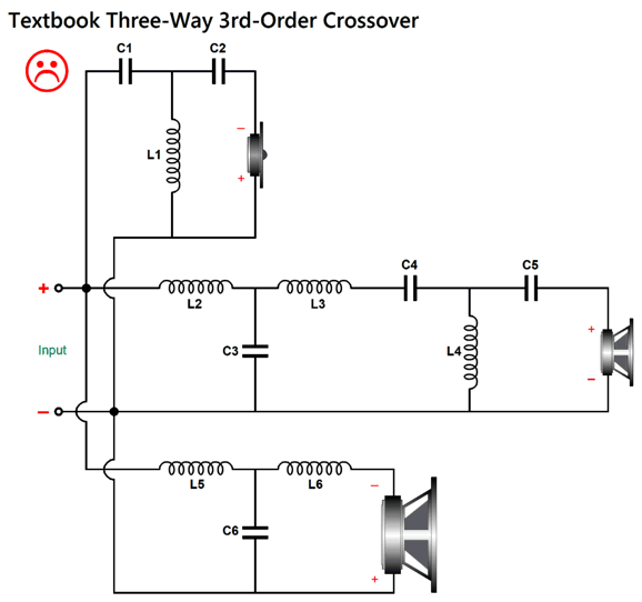
The most common workaround is to build a three-way loudspeaker, with a midrange helping to soften the sharp transition from the big, heavy woofer and small, light tweeter, as the midrange driver is lighter and smaller than the woofer, while being heavier and bigger than the tweeter. Moreover, the midrange allows us to raise the tweeter's crossover frequency, which places its Fs frequency further away from the crossover frequency. An additional workaround is to use a steep 3rd-order crossover with the three-way loudspeaker, thereby reducing the need for a wide overlap of frequencies. Promising as this workaround appears, we run into a new problem: textbook 3rd-order passive crossovers deliver neither a flat frequency nor impedance plot.
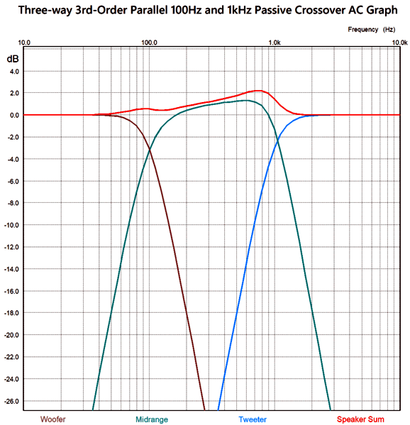
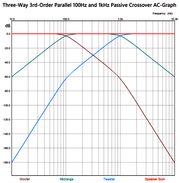
The big problem is that midrange portion of the crossover is not properly loaded, as the first half, the low-pass portion, is not loaded by an 8-ohm load. Using the crossover frequencies of 100Hz and 1kHz, the following is a SPICE-generated frequency graph for the circuit.
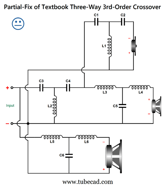
We can fix the midrange portion by simply rearranging the crossover topology.
In this tweeter-cascade arrangement, the midrange portion of the crossover is properly loaded, as its low-pass portion is now loaded by an 8-ohm load. As a nice bonus, the tweeter now sees two 3rd-order high-pass filters in cascade, thereby increasing its safety. Nonetheless, the resulting frequency response is not flat.
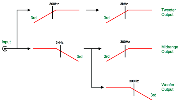
The bump has moved down to the first crossover frequency, as the woofer puts out too much output. The required workaround is to add an additional 3rd-order low-pass filter to the woofer. Here is the overview:
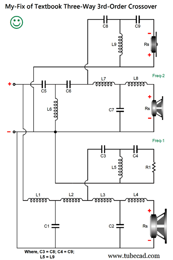
This arrangement is easy in a tri-amped setup with active crossovers, but can also be accomplished passively.
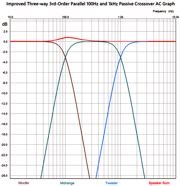
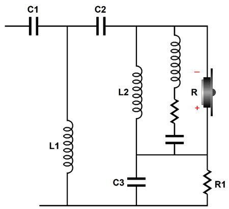
Resistor R1 seemingly does nothing, but R1, C3, C4, and L5 are essential, as they maintain a flat impedance plot and allow the woofer to see two low-pass 3rd-order filters in cascade. The midrange's SPL must be tad higher to compensate for resistor R1 not producing any sound, but not by much. For example, with the upper crossover frequency (Freq-2) being ten times higher than the lower crossover frequency, the needed increase is 0.009dB.
Note the wonderfully symmetrical two-slope cutoffs for both the woofer and tweeter. This is precisely what we desire, as we get the turgid woofer and the delicate tweeter out of the midrange as quickly as possible. Okay, it's now time to think outside the speaker box.
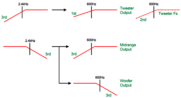
What if we set the crossover frequency between the woofer and the midrange to match the tweeter's Fs frequency? Now, the tweeter would see a cascade of its own mechanical resonant frequency 2nd-order high-pass filter with the passive crossover's first crossover frequency. This gets us close to the desired two 3rd-order cascade. Adding a 1st-order filter at the Fs frequency would push us over the finish line. Let's assume that Fs equals 600Hz, and that the crossover frequency between midrange and tweeter is 2,400Hz. The woofer sees the two 3rd-order filters in cascade, as does the tweeter, since the 1st-order 600Hz filter combines with the tweeter's intrinsic 2nd-order rolloff at Fs. Although this setup is easy to achieve with active crossovers, it took me some effort to create a passive equivalent.
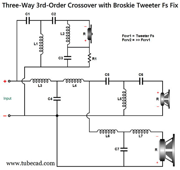
The added components of C3, L2, and R1 impose a 1st-order high-pass filter upon the tweeter. Effectively, the tweeter and resistor R1 are setup in a series two-way crossover tuned to tweeter's Fs frequency. Here are the design-example part values filled in:
The 3rd-order crossover alignment is the Butterworth and all the drivers are down -3dB at their primary crossover frequency. The math behind the part values can be gleaned from the following schematic:
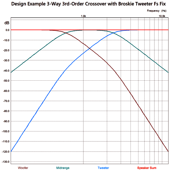
SPICE simulation shows the results for the design-example, three-way crossover which includes the Tweeter's own intrinsic Fs 2nd-order filtering:
By the way, the crossover assumes that the tweeter does not exhibit a big impedance peak at its resonant frequency. If it does, then an impedance-flattening circuit should shunt the tweeter. Three extra parts are needed.
This circuit is also known as the "series notch filter," which is a poor name choice, as the circuit does not alter the frequency response, only the impedance plot. In summary, my fix not only flattens the frequency and impedance plots, it adds further protection to the tweeter due to the added 1st-order high-pass filter. Next time, I will show how we can add an Fs fix to a three-way 2nd-order crossover. (Just imagine if I were a patent attorney. Imagine my submitting weekly patents, year after year….)
Music Recommendation:
Joshua Redman's Where Are We
The album has the theme of location, as in American cities, hence the title, Where Are We. I only knew four of the songs, and I took comfort that the song Do You Know the Way to San Jose? didn't make the list (on second thought, I bet Gabrielle and Joshua could pull it off). Here are the album's tracks:
The recording is excellent; in fact, I hope Redman sticks with the Blue Note label for all his future recordings. Highly recommended.
//JRB
User Guides for GlassWare Software
For those of you who still have old computers running Windows XP (32-bit) or any other Windows 32-bit OS, I have setup the download availability of my old old standards: Tube CAD, SE Amp CAD, and Audio Gadgets. The downloads are at the GlassWare-Yahoo store and the price is only $9.95 for each program. http://glass-ware.stores.yahoo.net/adsoffromgla.html So many have asked that I had to do it. WARNING: THESE THREE PROGRAMS WILL NOT RUN UNDER VISTA 64-Bit or WINDOWS 7, 8, 10, and 11 if the OS is not 32-bit or if the OS is 64-bit. I do plan on remaking all of these programs into 64-bit versions, but it will be a huge ordeal, as programming requires vast chunks of noise-free time, something very rare with children running about. Ideally, I would love to come out with versions that run on iPads and Android-OS tablets.
|
I know that some readers wish to avoid Patreon, so here is a PayPal donate button instead. Thanks. John Broskie
John Gives
Special Thanks to the Special 86 To all my patrons, all 86 of them, thank you all again. I want to especially thank
I am truly stunned and appreciative of their support. In addition I want to thank the following patrons:
All of your support makes a big difference. I would love to arrive at the point where creating my posts was my top priority of the day, not something that I have to steal time from other obligations to do. The more support I get, the higher up these posts move up in deserving attention.
If you have been reading my posts, you know that my lifetime goal is reaching post number one thousand. I have 411 more to go. My second goal is to gather 100 patrons. I have 14 patrons to go. Help me get there.
Only $9.95
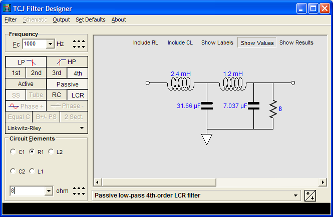
The Tube CAD Journal's first companion program, TCJ Filter Design lets you design a filter or crossover (passive, OpAmp or tube) without having to check out thick textbooks from the library and without having to breakout the scientific calculator. This program's goal is to provide a quick and easy display not only of the frequency response, but also of the resistor and capacitor values for a passive and active filters and crossovers. TCJ Filter Design is easy to use, but not lightweight, holding over 60 different filter topologies and up to four filter alignments: While the program's main concern is active filters, solid-state and tube, it also does passive filters. In fact, it can be used to calculate passive crossovers for use with speakers by entering 8 ohms as the terminating resistance. Click on the image below to see the full screen capture.
Tube crossovers are a major part of this program; both buffered and un-buffered tube based filters along with mono-polar and bipolar power supply topologies are covered. Available on a CD-ROM and a downloadable version (4 Megabytes). Download or CD ROM
|
|||


| www.tubecad.com Copyright © 1999-2023 GlassWare All Rights Reserved |