| John Broskie's Guide to Tube Circuit Analysis & Design |
21 November 2023 Post Number 590
That's certainly a provocative title. Yet, if you think about it, this title applies to just about every post I have made the last 24 years. Okay, what the audio world needs is a two-stage, two-voltage AC switch. Most countries run a mains AC voltage of either 120Vac or 230Vac. (In Japan, they run 100Vac; Caribbean nations, 110Vac; Mexico, 127Vac; South Korea, 220Vac; Kenya, 240Vac.) Thus, it behooves transformer manufactures to make power transformers with dual primaries, as they can be used with either 120Vac or 230Vac wall voltages.
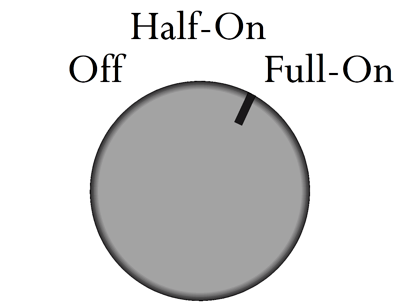
The two primaries can be wired up either in series or in parallel. (You sometimes see a switch on the back of electronic gear that allows the switching of the input mains voltage to suit the locality.) In contrast, switching power supplies usually do not care what your wall voltage is, as they can accept AC voltage from 90Vac to 300Vac. In the world of audio, we tend to prefer transformer-based power supplies to switching power supplies. I once took advantage of the power transformer's dual primaries in my solid-state power amplifier by wiring it up as if I lived in Europe, so I effectively halved the bipolar power supply voltages. Why? I wanted to experiment with twice the idle current in the MOSFET output stage, but not over tax the heatsinks. Here is the idea: first we must live in a 120Vac country; next, we need a three-position power switch that offers three outputs, off, half-on, and full-on. What good would that be? Such an arrangement allows the power supply voltage to develop in two stages: low and high. The power-supply reservoir capacitors initially see half the expected DC voltage, which allows them to adjust to being charged before the full DC voltage hammers them.
Tube-based audio gear will be much happier, as the heater elements will not see nearly the huge inrush of current. (A cold heater draws far more current than when it is hot.) In physics books, we learn that magnetic pressure force caused by high current flow stretches wire, which over time can cause a filament to thin and break. Compared to 50Hz or 60Hz AC voltage, people are slow. In other words, even if you quickly spin the rotary switch from off to half-on to full-on, enough time to will have lapsed to give the two-stage AC voltage ramp-up to occur. Do not forget that if you double the voltage, you quadruple the wallop.
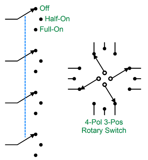
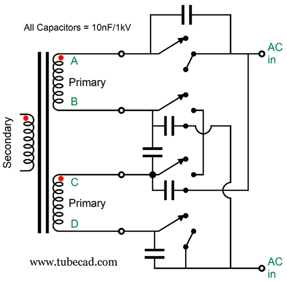
A three-position rotary switch is needed, along with dual transformer primaries.
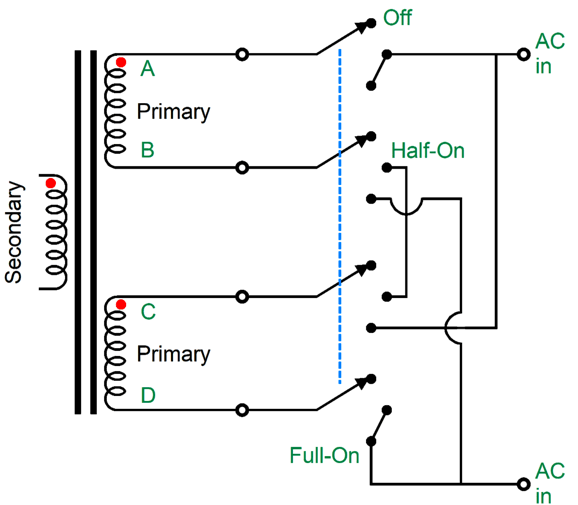
The rotary switch holds four poles, all of which move in tandem. Next, we wire the contacts up thus:
As you can see, all the interesting action happens with the B and C wires, as the A and D wires always connect up to the same AC connection. In the off position, both primaries are left floating, with no connection to the wall voltage. In the center position, wires B and C are tied together, so the two primaries are in series, and only half of the secondary AC voltage develops. In the extreme on position, the primaries are in parallel, so the full secondary AC voltage develops. What's missing from this schematic is AC-snubbing capacitors. When a switch contact breaks its connection, any inductance in the circuit will cause arcing and RFI creation. The workaround is adding capacitors that eliminate the voltage transient and ringing that occurs when the switch opens by providing an alternate path for the current flowing through the circuit’s intrinsic leakage inductance.
The added 10nF (0.01µF) ceramic capacitors absorb what would have been switching noise. In many countries, these capacitors are required by law. We could go further and place a 10-ohm low-inductance resistor in series with each capacitor. Remember that energy is never destroyed; it is only transformed. The added resistors turn arcing energy into heat.
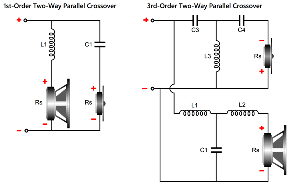
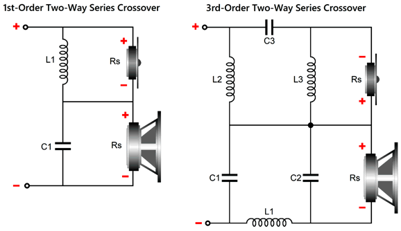
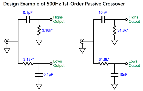
1st-Order Crossovers with Fs Fix
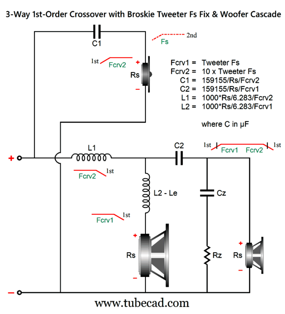
I cannot come up with a fix for passive two-way crossovers, whereas three-ways crossovers allow more freedom. Let's start with the three-way, 1st-order crossover.
The midrange needs to 1.6dB higher in SPL per watt than the woofer and tweeter. The woofer and the midrange are arranged in 1st-order series topology, but the tweeter and the woofer-midrange combo are arranged in the parallel setup. If we want to go full parallel, the following is the path to follow.
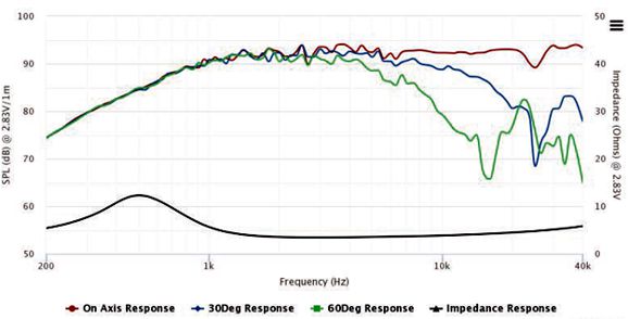
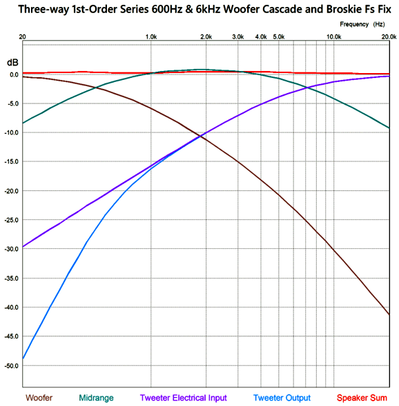
I prefer the former circuit, as I like having the midrange and woofer shunted over the portion of the audio bandwidth wherein they get in trouble. On the other hand, the full-parallel arrangement does allow us to use the woofer's series inductance (Le) as part of the crossover's design. With crossover frequencies of 600Hz and 6kHz, the following graph shows the results.
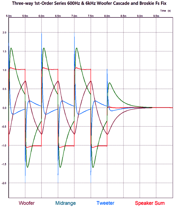
The frequency plotline for the sum of all three drivers is close to perfectly flat. The best test for phase flatness is a burst of square-waves.
There are several things to note here. The first is that the resulting square waves are not perfect, but nonetheless vastly better than any 2nd-order or 3rd-order or 4th-order crossover—all of which garble the phase. The square-wave frequency is 1kHz with +/-1V peak, yet the tweeter sees a peak input voltage of nearly 2V. The midrange also sees more than 1Vpk, while the woofer sees less than 1Vpk.
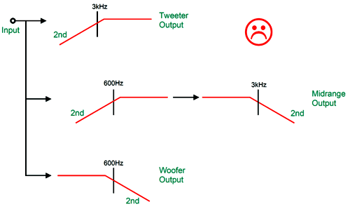
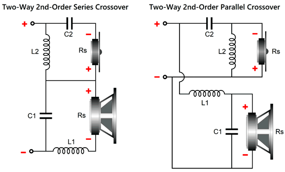
2nd-Order Crossovers with Fs Fix When making a three-way 2nd-order Linkwitz-Riley crossover things get tricky. For example, the following arrangement results in droop in the midrange.
If we implement this crossover arrangement actively, with capacitors and resistors and OpAmps, which approaches the ideal far more than any actual passive crossover made capacitors and inductors can ever match, we clearly see the dip in SPICE simulations.
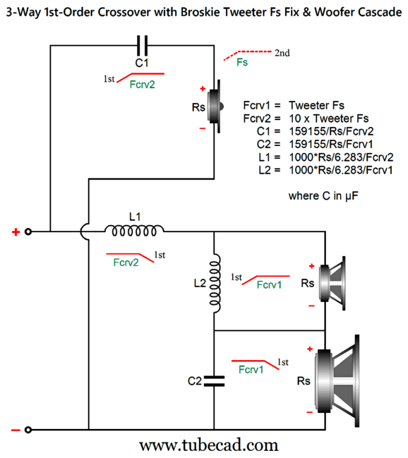
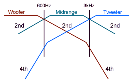
If we use a midrange with a slightly higher SPL relative to the woofer and tweeter, the dip can be filled in quite easily. The bigger problem is that these plotlines assume perfect loudspeaker drivers with flat frequency response from 20Hz to 20kHz. Such ideal drivers simply do not exist. The tweeter's resonant frequency falling within the mid-band of audio frequencies is just one obvious problem. An alternative arrangement is to have a woofer and tweeter cascade, wherein these drivers see two 2nd-order filters in series.
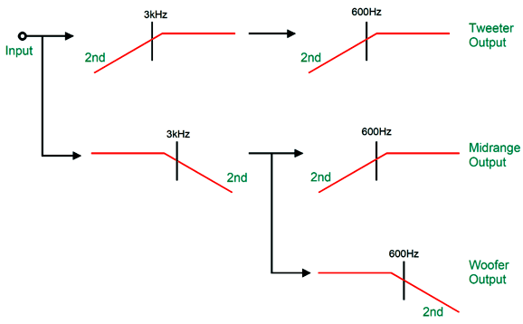
The midrange sees constant 2nd-order cutoff slopes, while the woofer and tweeter see two-stage slopes. Making this arrangement happen is not that difficult, as we need only cascade the filters.
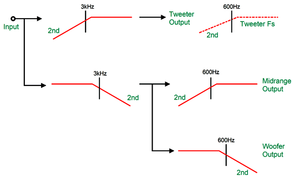
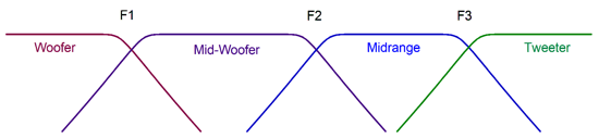
If you compare this overview to the previous one, you see that only one additional filter section (600Hz high-pass) was needed. On the other hand, if we set the crossover frequency between the woofer and midrange to the tweeter's Fs frequency, say 600Hz, we effectively get a free 2nd-order high-pass filter.
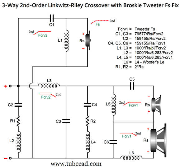
Okay, let's return to passive crossovers and real drivers. First, we must ensure that the woofer gets its cascade of low-pass filters. Second, all drivers must share the same impedance.
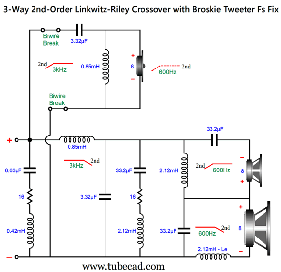
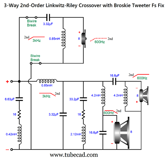
This is a combination of parallel and series crossovers. I like this arrangement as it allows the woofer's own intrinsic series inductance (Le) to become part of the crossover, thereby eliminating the need for a Zobel network across the woofer. (The midrange driver, however, should get its own Zobel network.) Moreover, we can easily set this crossover up for bi-wiring. Here is a design example with 600Hz and 3kHz as crossover frequencies.
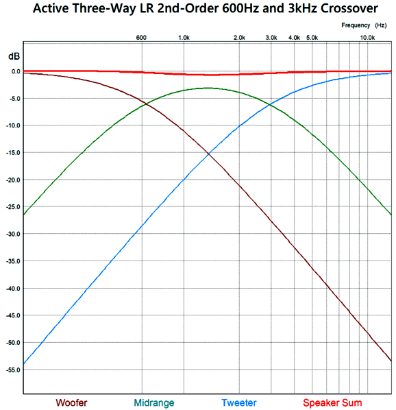
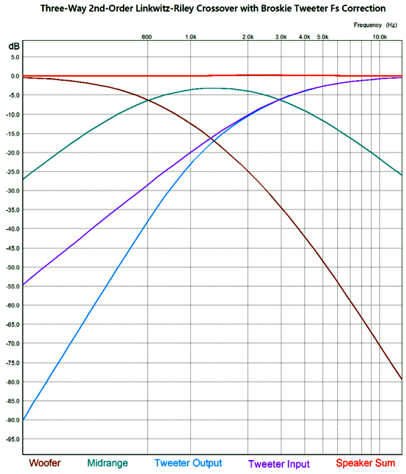
By the way, the resistors must be power types. For example, R1 can be a 3W and R2 a 10W. The following is a SPICE-generated graph that shows how well this crossover works at fixing the tweeter's Fs problem.
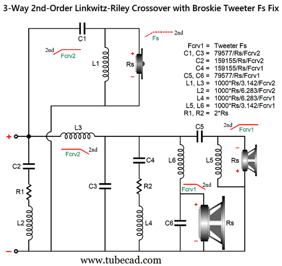
(The midrange driver should be 0.5dB higher in SPL than the woofer and tweeter.) Note that the tweeter's acoustic output differs from its electrical input. In other words, although the tweeter behaves as if it saw two high-pass filters in series, it does not realize the added benefit of increased safety that two filters in cascade implies. On the other hand, the woofer does receive a two-slope high-frequency cutoff. Some cannot wrap their heads around series crossover topologies, so here is the pure parallel version.
One of the usual advantages of a parallel crossover topology, i.e. the ability to use dissimilar driver impedances, does not obtain here, as the two impedance-flattening networks, C2 & L2 & R1 and C4 & L4 & R2, assume the same driver impedances throughout. Here is a design example with, once again, 600Hz and 3kHz as crossover frequencies.
Both the woofer and midrange driver should get Zobel networks. Note that with the Linkwitz-Riley parallel topology the capacitors are half of what a 1st-order crossover would use, while the inductors are twice the 1st-order values. Here is a design example.
What about four-way 2nd-order crossovers? To be frank, often we can ignore the problem of the tweeter's Fs frequency in a four-way system, no matter what the crossover order, as long as the crossover frequency to the tweeter is much higher than its Fs frequency. In contrast, in two-way loudspeakers, the problem of the tweeter's Fs frequency is far more acute. Sadly, I cannot think of a passive-crossover solution to the Fs problem with a two-way passive crossover—other than to use a dual-voicecoil woofer, which would effectively make a two-driver, three-way system. On the other hand, I have devised an active two-way crossover that overcomes the problem.
2-Way 2nd- and 3rd-Order Active Crossovers with Fs Fix
In reality, it will be phase shifted by 90 degrees at its Fs frequency. In addition, most published driver phase plots show the phase shifting away from the Fs frequency in both directions, then returning to zero. This is nonsense. How so? If it were true, then a woofer would always push forward when attached to a battery, regardless of the polarity connections. To get the woofer and tweeter to meld correctly requires that the woofer undergoes a similar phase shift at the tweeter's Fs frequency as does the tweeter. This desired outcome is only possible with an active two-way crossover, as we can easily incorporate a frequency-dependent phase-shifting circuit to the active crossover. Active two-way crossovers imply a bi-amp setup, wherein the two drivers each get its own power amplifier. No more big passive-crossover capacitors and inductors—wonderful to relate. Sadly, giving a tweeter its own directly-coupled power amplifier can be dangerous. How so? Hum and turn-on and turn-off thumps. Imagine a 100W solid-state power amplifier directly attached to a tweeter. Now imagine your cat stepping on the interconnect that attaches to the power amplifier, thereby pulling away the outer ground connection, but leaving the inner signal plug still making contact, resulting a huge 100W of amplifier output at 50Hz or 60Hz. You do not, however, need to imagine the cursing and anguished cries. The workaround to this dangerous situation is to give the tweeter a coupling capacitor that is small enough in value to protect the tweeter but not so small as to interfere with the active crossover's output. The smart approach is to make this added capacitor part of the crossover design.
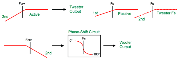
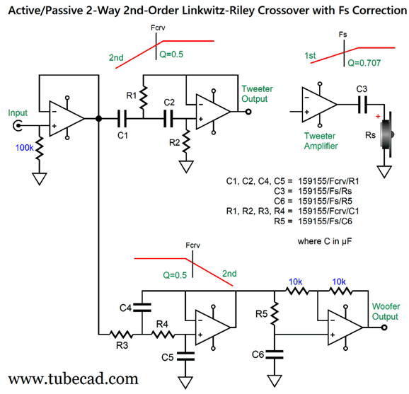
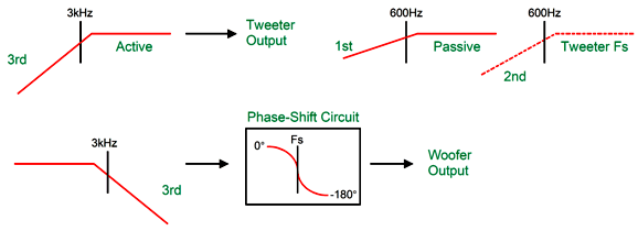
The added coupling capacitor and the tweeter's own resonant frequency combine to create a 3rd-order high-pass filter. The phase-shifting circuit is tuned to the tweeter's Fs frequency, and the woofer undergoes the same phase shift as the tweeter. The tweeter initially outputs a 2nd-order slope and then a 5th-order slope below its Fs frequency. In electrical terms, the tweeters input signal slopes off 2nd-order and then steepens to 3rd-order below its Fs frequency.
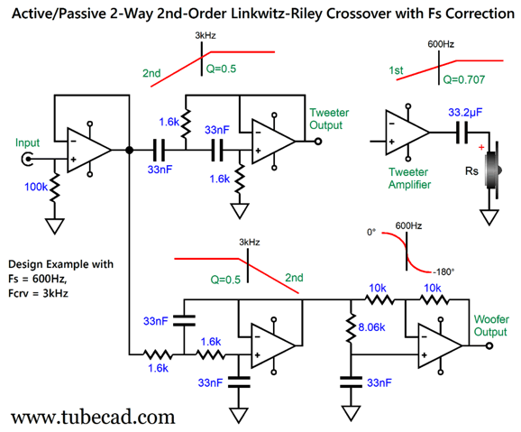
If the signal source, such as a line-stage amplifier or DAC, offers a low output impedance, the input buffer stage is not needed. Here is a design example:
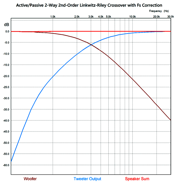
Note the 33.2 µF coupling capacitor that separates the power amplifier from the tweeter. Of course, if your preference is for supremely expensive boutique capacitors, this capacitor might cost far more than then power amplifier—such is the non-linear world of linear electronics in high-end audio. I would use a quality 33µF polypropylene-film capacitor shunted with a fancy 0.22µF capacitor. By the way, if the tweeter exhibits a big impedance spike at its resonant frequency, an impedance-flattening network should be used. (See my last post.) Here is the SPICE-generated frequency graph for this crossover.
I can imagine such a setup, a setup with a directly coupled power amplifier, working well in a two-way loudspeaker that held a planar or AMT tweeter, as these non-dome tweeters often allow a much lower crossover frequency and are usually much more robust than delicate dome tweeters. In contrast, with either a horn or a dome tweeter with a low Qms, I would use the following 3rd-order version.
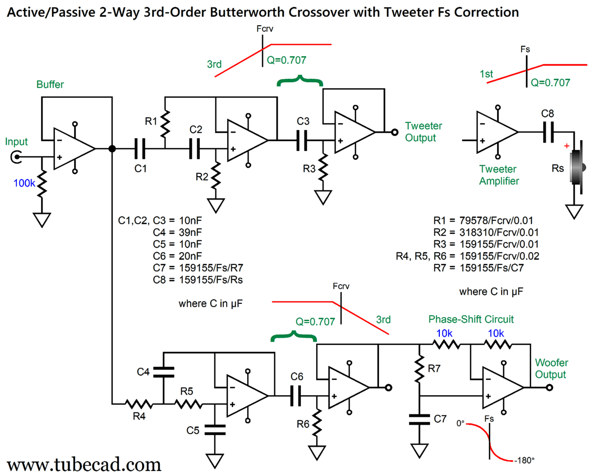
The crossover slopes are now 3rd-order and the alignment is Butterworth, not Linkwitz-Riley. The tweeter still gets its 1st-order capacitor. (Other crossover frequencies and Fs frequencies are, of course, possible, but I just had those frequencies in mind when I made the graphic.)
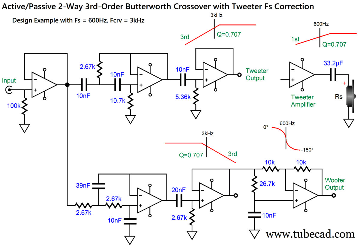
Three dual-OpAmps per channel are needed. The preset capacitor values of C4 through C6 follow a ratio of 4, 1, 2 that conforms to the Butterworth alignment and, importantly, use readily available capacitor values. Yes, 39nF should be 40nF, but it is dang close and 39nf can be bypassed by a 1nF capacitor. Mind you, 39nF is only off by 2.5% and it's hard to find capacitors in tolerances below 3%. In other words, a 3% 39nF capacitor might measure 40nF. Here is a design example:
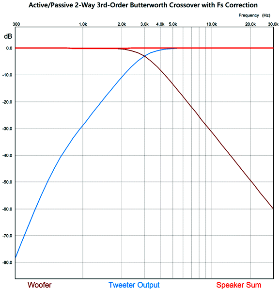
The resulting frequency plots show the steeper slopes. Unlike 2nd-order and 4th-order Linkwitz-Riley crossovers, the 3rd-order Butterworth has the two drivers down -3dB at the crossover frequency.
Yes, there is a slight dip between 800Hz and 2.2kHz, due to the tweeter's failing to provide flat output at lower frequencies, but this dip is nothing compared to actual speaker driver frequency irregularities.
If the tweeter's Qms is high, say anything above 2, I would forgo the safety of the 33.2µF coupling capacitor in the previous design examples. Why? A loudspeaker driver's total Q (Qts) is the result of placing its mechanical Q (Qms) and its electrical Q (Qes) in parallel. This derived attribute, Qts, only holds true if the driver is shunted by zero ohms—a short length of thick copper wire is close enough. With the tweeter's voicecoil left floating, however, only the Qms remains. The higher the Qms, the less stable the driver is at its resonant frequency. A 33.2µF capacitor presents an impedance of 8 ohms at 600Hz, which is very different from zero ohms. In other words, if the tweeter's Qms is high, and if it is effectively unloaded at its Fs frequency, it will resonate boldly. In contrast, directly coupling the tweeter to a solid-state power amplifier more closely approximates a dead short across its leads; thus, the full Qes damping applies. This problem also applies to conventional passive crossovers. For example, both the 1st-order and 3rd-order parallel crossover topologies unload the tweeter. As the frequency fall near the Fs frequency, the tweeter becomes unloaded due to the capacitor; in addition, the woofer becomes unloaded at high frequencies due to the series inductor.
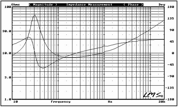
In contrast, the series odd-order crossovers do provide tweeter shunting. As long as the tweeter's Fs frequency is far enough below the crossover frequency, the inductor's impedance will be much lower than the tweeter's impedance at its Fs frequency. In fact, at its Fs frequency, the tweeter's impedance will peak, say to 40 ohms, while the inductor's impedance will fall, say to 1.6 ohms.
In contrast, the series odd-order crossovers do provide tweeter shunting. As long as the tweeter's Fs frequency far enough below the crossover frequency, the inductor's impedance will be much lower than the tweeter's impedance at its Fs frequency. In fact, at its Fs frequency, the tweeter's will peak, say to 40 ohms, while the inductor's impedance will fall, say to 1.6 ohms. With even-order 2nd-order series crossovers, however, the tweeter is denied shunting. In contrast, the 2nd-order parallel crossover does provide shunting.
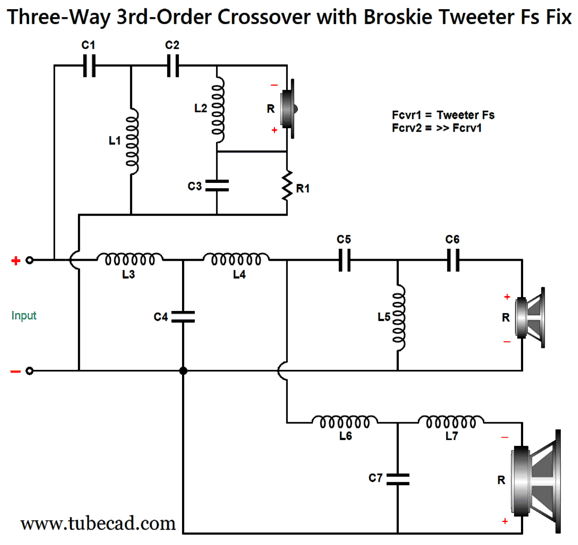
While on this topic, I should point out that my last post's Fs fix for 3-way, 3-order crossovers has the effect of loading the tweeter at its Fs frequency. Inductor L2 and capacitor C3 are tuned to the tweeter's Fs frequency, not the crossover frequency between the tweeter and the midrange driver.
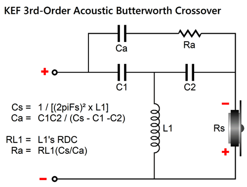
Note how L2 effectively shunts the tweeter at its resonant frequency. By the way, if we add Zobel networks across the woofer and midrange driver, we also are adding some damping at high frequencies. If you have access to the 1989 issue 5 of Speaker Builder magazine, you can read an article by Jorge Oliveira, titled "Tweeter Q Problems," wherein he describes the Qms problem and the KEF workaround for the 3rd-order Butterworth parallel crossover:
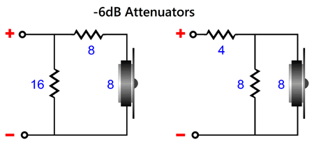
By the way, the capacitor values are in farads, not µF; the inductor values, henries, not mH. The point behind this variation is to force a dip in tweeter output at its Fs frequency. We should examine the shunting effect of L-pad attenuators, which come in two flavors.
Both versions yield the same attenuation and present the same load impedance to the crossover, but the one on the right delivers 8 ohms of tweeter shunting resistance, while the one on the left only delivers 24 ohms. (This assumes a crossover capacitor in series with the tweeter attenuator.) Depending on whether we desire less or more damping, each style might find its preferred application. Although both versions deliver the same attenuation, they might sound very different! (My English teacher only allowed one—and only one— exclamation point per essay, as he deemed anymore as a hysterical affect.) The take away here is that there is no easy answer to the question, which is the best passive crossover type? It depends—the only possible answer. Is the power amplifier a voltage-out or current-out type? Does the tweeter exhibit a low Qms or a high Qms?
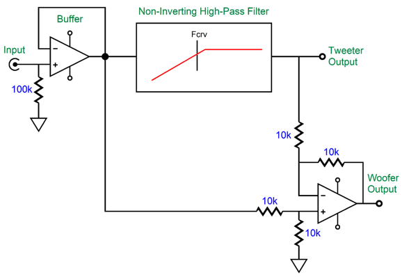
This active crossover type has been covered in previous posts, such as posts 474, 475, 581. In fact, these previous posts included fixes for the tweeter Fs problem. What follows is a fine-tuning of the fix. The assumption has been that the tweeter's total Q factor (Qts) was 0.707, which is the Q of a Butterworth filter. Typically, tweeter Qts can be a low 0.2 to a high 2. For example, the Peerless DA32TX00-08 1" dome tweeter exhibits a Qts of 0.56, while the ScanSpeak D2608-9130's Qts is 0.29. At the other extreme, the Dayton Audio AMTPRO-4 air-motion-transformer tweeter sports a Qts of 4.12! (As my old English teacher is most likely dead now, I will risk this indulgence.) Let's start with a quick recap of the active asymmetrical phase-flat crossover.
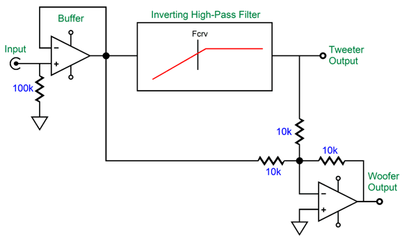
An OpAmp strives to maintain the same voltage at both its inputs, using its considerable open-loop gain to bring the two inputs into voltage alignment. Thus, when we look at the above schematic we know that input signal will be halved at the OpAmp's non-inverting input, as the signal must pass through a two-resistor voltage divider with equal-valued resistors. We also know that this same halved input signal must appear at the non-inverting input.
This means the OpAmp's output signal has to be a perfect complement and counterpart to the high-pass filter's output—as this is the only way the two outputs can sum to the original input signal at the OpAmp's inverting input. Since the high-pass filter output lacks bass frequencies, the bottom OpAmp's output must provide the missing bass frequencies in the just the right amplitude and phase relationship to achieve the perfect summation. Since the high-pass filter output does provide the high frequencies, the crossover's woofer output does not need to supply these frequencies, which creates the low-pass filter action on the woofer output. This arrangement yields a symmetrical pair of outputs, only when the high-pass filter is 1st-order.
You might wonder why would anyone bother with this elaborate arrangement to create a 1st-order crossover when just two RC filters are needed? Precision. We can readily buy 0.1% resistors. (Even if 0.1% capacitors were sold, it's unlikely that they would remain 0.1% on the target capacitance after being soldered, due to the small physical deformities resulting from the intense heat.) If you need a perfect active 1st-order, two-way crossover this is the way to go. By the way, here "perfect" does not mean perfectly on the target crossover frequency, but the perfect summing of the two outputs to match the input signal. For example, the target crossover might be 1kHz, but a 3% capacitor might result in a crossover frequency of 1030Hz. Nonetheless, the differential OpAmp will perfectly match this frequency; in contrast, the two-RC-filter approach might produce 970Hz as the low-pass filter's crossover frequency, creating a 60Hz misalignment in crossover frequencies. In addition, your tastes might incline to $2,000 coupling capacitors made from platinum foil and whale oil. Thus, this single-capacitor 1st-order active crossover saves enough money to purchase four $500 RCA jacks. If the high-pass filter inverts the input signal phase at its output, the following topology is needed.
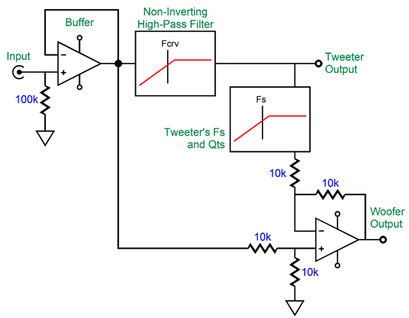
The sum of these two outputs is also frequency flat and phase flat, but inverted by 180 degrees, which is no big deal, as the line-stage amplifier might have already inverted the signal, and we can always flip the phase at the amplifier output terminals. We can include more than just the high-pass filter to be complemented by the woofer's output, such as the tweeter's Fs frequency and its Qts.
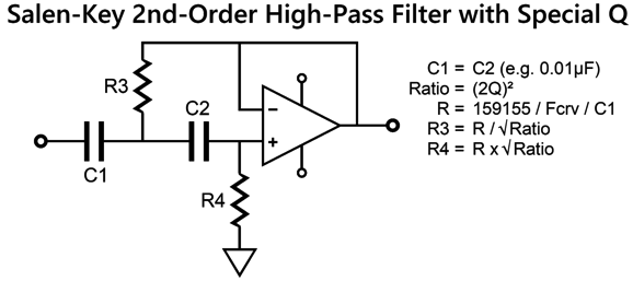
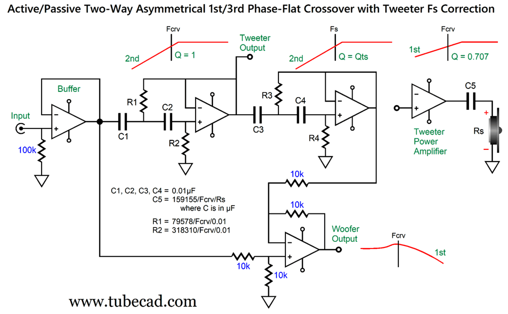
The tweeter's power amplifier still gets its high-pass filtered signal, just as a typical active crossover would deliver, but the bottom OpAmp, which is configured as a differential amplifier, now has a more accurate picture of what the tweeter will actually put out acoustically. To create an electronic equivalent of the tweeter's acoustic output we need build a 2nd-order high-pass filter with the same filter frequency and Q as the tweeter's Fs and Qts. The easiest non-inverting active filter that meets these requirements is the Salen-Keys topology.
By the way, the formulas require that C1 is in µF. For example, if the tweeter's Qts is 0.3, the resistor ratio equals (2 x 0.3)² or 0.36. Next, we find R's value by dividing 159155 by the tweeter's Fs frequency, say 500Hz, and then further dividing by C1's value, say 0.01µF, which would give us 31831. Resistor R3 will then equal 31831/0.36, while R4 will equal 31831 x 0.36. Once we have worked out these values, we can plug them to the following schematic.
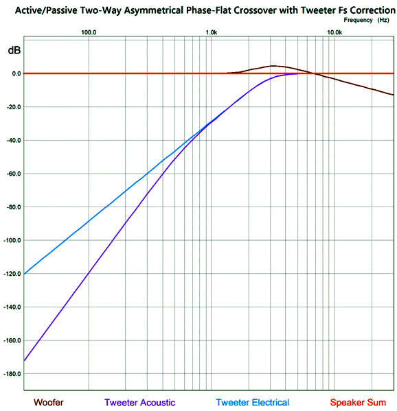
The tweeter effectively sees a 3rd-order Butterworth (Q = 0.707) cutoff at the crossover frequency, as the active 2nd-order adds to the passive 1st-order filter, while its acoustic output falls off at a 5th-order slope below its Fs frequency.
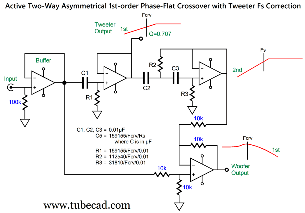
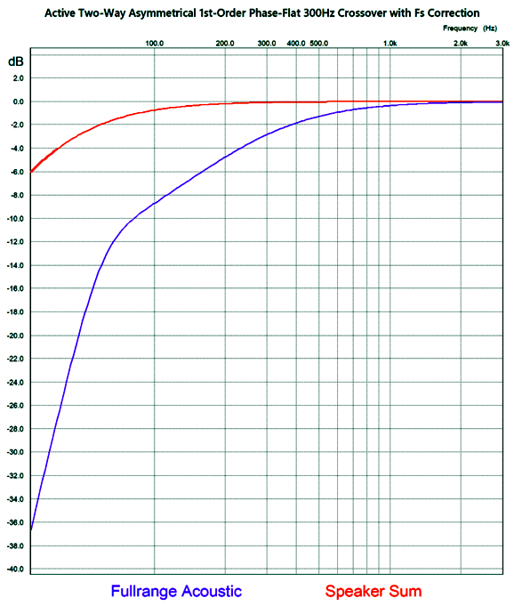
The crossover frequency is 3kHz. Note that woofer's rolloff is supremely shallow. In other words, a fullrange driver should be used in place of the typical woofer with this high a crossover frequency. On the other hand, if the crossover frequency were 800Hz, we could probably get away with a conventional woofer. By the way, the active asymmetrical phase-flat crossover can be flipped, so the woofer gets the 3rd-order low-pass filter, while the "tweeter" gets the bumpy, shallow rolloff at a 1st-order slope. I put the quotation marks around "tweeter" as I would never use a tweeter in this setup; instead, single fullrange driver or a mini-monitor two-way loudspeaker would take the place of the tweeter, as a low (200Hz to 500Hz) crossover frequency would be used. Here is a possible example: the woofer is in sealed box that exhibits an Fc of 30Hz. The fullrange driver presents an Fc in its small sealed box of 60Hz and a Qc of 0.8. We then use the setup with a 1st-order crossover frequency of 300Hz.
The fullrange driver sees a 1st-order cutoff below 300Hz, then a 3rd-order slope below 30Hz. The woofer's signal compensates for the fullrange driver's lack of low-frequency extension.
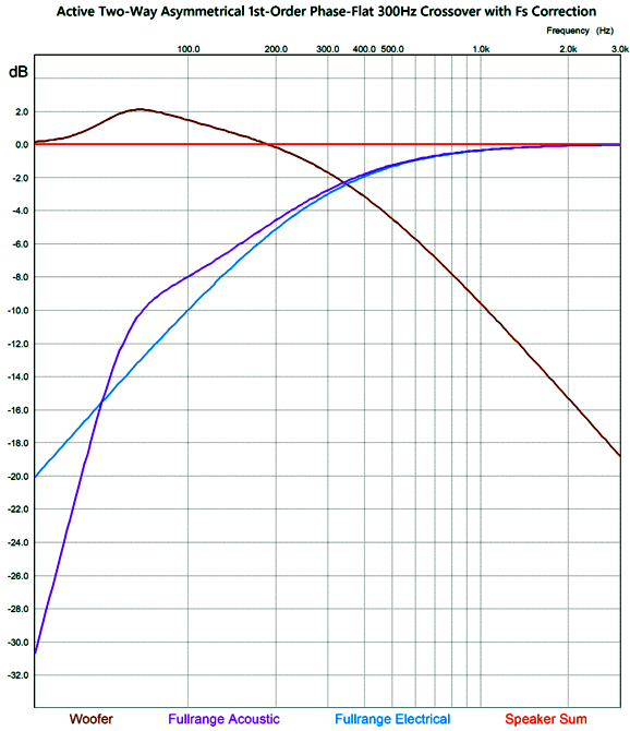
The 30Hz cutoff was not included in this simulation, so the summed plotline will begin to fall off at around 40Hz. Note the over 2dB bump in the woofer's output. Now, we include the woofer's Fc 30Hz cutoff.
The summed output's -3dB frequency is 47Hz. The third fullrange driver rolloff cannot be seen due the graph starting at 30Hz. In addition, the woofer's power amplifier still sees the +2dB bump, although the woofer's output softly rolls off.
Music Recommendation: Northscapes
This is a good thing, as I have little desire to actually visit the ice in person. Yet, arctic inspired classical music is hot today. And I am all for it. I have always loved Russian music and, over thirty years ago, I happily discovered Estonian composer, Arvo Pärt; and a decade later, Erkki-Sven Tüür. In fact, Post 511 recommended Concurrence, an album by the Iceland Symphony Orchestra, conducted by Daníel Bjarnason; post 527, Anna Thorvaldsdottir's album, Aerial. Northscapes features piano compositions played by Lithuanian pianist Ieva Jokubaviciute. Denmark, Norway, Finland, Latvia, and Lithuania—all contribute compositions, which are varied enough elude the boredom that some collection albums produce. Moreover, the recording is excellent. Amazon Music and Qobuz both offer the album in 24-bit, 96kHz resolution. Pour yourself a cup of eggnog, light a log in your fireplace, and have a listen.
//JRB
Did you enjoy my post? Do you want to see me make it to post 1,000? If so, think about supporting me at Patreon.
User Guides for GlassWare Software
For those of you who still have old computers running Windows XP (32-bit) or any other Windows 32-bit OS, I have setup the download availability of my old old standards: Tube CAD, SE Amp CAD, and Audio Gadgets. The downloads are at the GlassWare-Yahoo store and the price is only $9.95 for each program. http://glass-ware.stores.yahoo.net/adsoffromgla.html So many have asked that I had to do it. WARNING: THESE THREE PROGRAMS WILL NOT RUN UNDER VISTA 64-Bit or WINDOWS 7, 8, and 10 if the OS is not 32-bit or if it is a 64-bit OS. I do plan on remaking all of these programs into 64-bit versions, but it will be a huge ordeal, as programming requires vast chunks of noise-free time, something very rare with children running about. Ideally, I would love to come out with versions that run on iPads and Android-OS tablets.
|
I know that some readers wish to avoid Patreon, so here is a PayPal button instead. Thanks.
John Broskie
John Gives
Special Thanks to the Special 85 To all my patrons, all 85 of them, thank you all again. I want to especially thank
I am truly stunned and appreciative of their support. In addition I want to thank the following patrons:
All of your support makes a big difference. I would love to arrive at the point where creating my posts was my top priority of the day, not something that I have to steal time from other obligations to do. The more support I get, the higher up these posts move up in deserving attention.
If you have been reading my posts, you know that my lifetime goal is reaching post number one thousand. I have 410 more to go. My second goal was to gather 1,000 patrons. Well, that no longer seems possible to me, so I will shoot for a mighty 100 instead. Thus, I have just 15 patrons to go. Help me get there. Thanks.
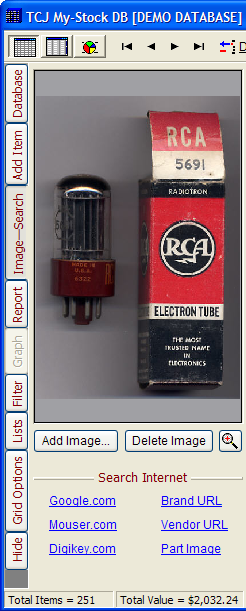
Only $12.95 TCJ My-Stock DB
Version 2 Improvements *User definable Download for www.glass-ware.com
|
|||


| www.tubecad.com Copyright © 1999-2023 GlassWare All Rights Reserved |