01 Febuary 2024 Post Number 595

We are close enough to my 600th post that I can almost taste it. We also near the Tube CAD Journal's 25th year anniversary. Both are staggeringly unbelievable to me.
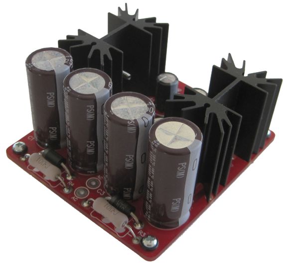
I have needed something like the new PS-25 for a long time. The PS-25 is a low-voltage, bipolar, voltage-regulated power-supply that is powered by a single secondary AC voltage, such as a 12Vac wallwart transformer or a regular power transformer secondary winding.
Here is why I need this low-voltage power supply: often tube-based circuits cannot provide either the low-noise or gain that is needed. For example, the Tetra phono preamp can easily deliver 40dB gain, but that is not enough for use with a low-output MC cartridge, which might need an extra 20 dB of gain. Well, most low-voltage toroid power transformers hold two secondaries, so one can be devoted to the heater power supply, which might be referenced to 75Vdc, leaving the other secondary to power the PS-25, which in turn can power an OpAmp circuit that will provide the needed low-noise 20dB of gain.
The PS-25's schematic shows how simple is the circuit.
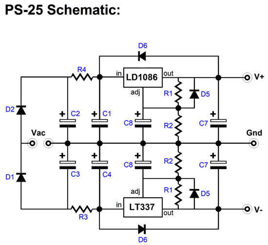
The parts used are fancy, not the circuit. The low-dropout (LDO) regulators, LD1086V positive and LT337AT negative, are used to establish the bipolar output voltages, which can be set to any voltage between ±5Vdc to ±24Vdc by selecting different values for resistors R2. The LT337 is a big upgrade to the LM337, which explains why it costs seven times more. The rectifiers (MUR410G) are the ultra-fast type and are arranged in a center-tapped voltage-doubler configuration. Two RC filters pre-filter the unregulated DC voltage.
This bipolar regulator requires a power transformer with a secondary voltage between 6.3Vac to 24Vac, depending on the output voltages required. Fortunately, unlike high-voltage transformers, low-voltage power transformers are easy to find. In fact an AC wallwart transformer works great in many applications. Use a power transformer with a current rating at least 3.6 times greater than the expected peak load current. A fuse can be placed either in series with the transformer primary or secondary.
Resistors R3 & R4 form RC filters with capacitors C2 & C4, which greatly enhance the performance of the voltage regulator, as they pre-filter the DC entering regulators, stripping away much of the rectifier hash and ripple. The higher the expected current draw, the smaller in value these resistors must be. In other words, OpAmp-based circuits draw little current, so 20-ohm resistors can be used, whereas a headphone amplifier would use 1-ohm resistors, possibly even lower-resistance resistors.
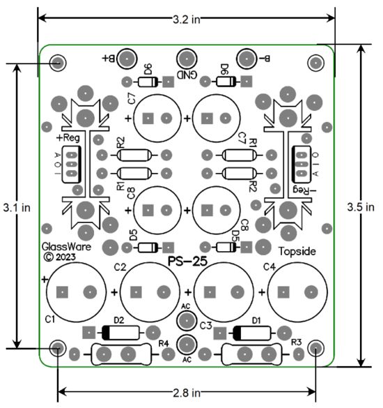
The PCB is 3.2in by 3.5in big and the heatsinks are either 1.5in or 2.5in tall.
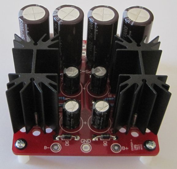
Although the LD1086V & LT337AT are rated for up to 1.5A of current flow, the biggest limitation is the heatsink, which limits maximum dissipation. See post 511 for details on how a 1.5-inch tall heatsink compares to a 2.5-inch tall heatsink. (In many ways, the PS-25 is descendent from the PS-22.)
The PS-25 kit is available now at the GlassWare web store.
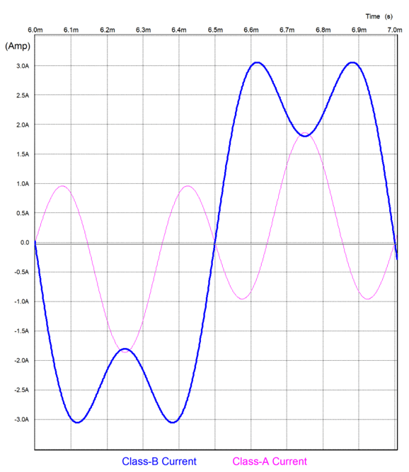
In my last post, I promised to reveal a new parallel power amplifier arrangement, and indeed I will. First, however, we must travel all the baby-steps required (and which I took) to get there. The "there" we desire is a marriage between two power amplifiers that work not in tandem, i.e. series like the class-S arrangement with one amplifier serving as a faux ground, but in parallel like the infinite-gain amplifier—but without the liabilities of the infinite-gain arrangement. Most importantly, the two amplifiers are not identical but differ, as one is forceful and efficient, but a bit clumsy, while its partner is exacting and precise, but inefficient and relatively weak. A good analogy is that of the wedding of brains with brawn—or, perhaps, vulgar wealth with refined beauty. This match-up cannot, however, be equitable, i.e. an arrangement wherein both contribute 50% of the output to the loudspeaker, as this arrangement buys us little. (Imagine a 50-50 mix of great wine with bad wine.)
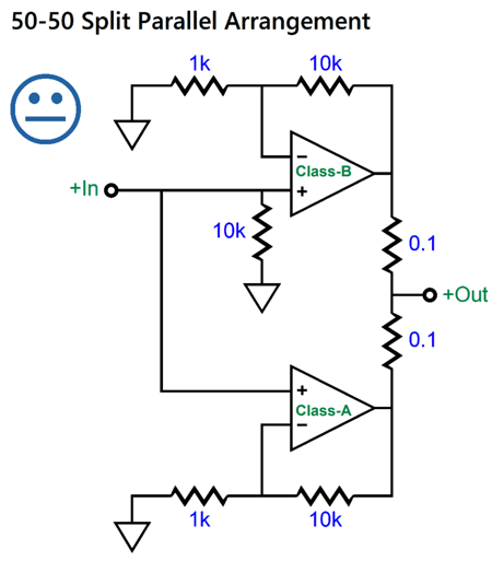
A class-B offers a maximum efficiency of 78%, while the class-A amplifier delivers a maximum of 50%. Combined, the resulting efficiency is a modest 64%. Worse, the combined THD only betters the class-B amplifier's contribution by maximum of a half. In other words, even if we assume the class-A power amplifier produces no harmonic distortion whatsoever, the mixing of the two outputs would only reduce the class-B amplifier's distortion by -6dB. Not much, especially when we considered the extra effort and cost. What we want is for the class-A amplifier to erase all of the class-B amplifier's transgressions, which must require the class-A to produce the exact same distortion as the class-B amplifier, but inverted, so the two distortion can cancel, much like too-hot water mixing with too-cold water or like +1 encountering -1.
If we extend the class-A amplifier's negative feedback loop to the summed output, the distortion does go down, but the class-B amplifier contributes nothing to the output other than adding some distortion that the class-A amplifier must clean up.
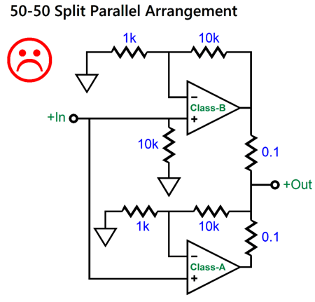
Why does the class-B amplifier not help drive the load? If both amplifiers are putting out 40Vpk, then the top 0.1-ohm resistor sees no net differential voltage, and, thus, it sees no current flow. If we try to rescue this arrangement by slightly increasing the gain of the class-B amplifier, so that this resistor does see a voltage drop, we transform the circuit into an infinite-impedance amplifier, and, as a result, encounter all the possible problems of an infinite-impedance amplifier (see my last post).
A further goal is that the class-A amplifier dissipate no more heat at idle than its class-B partner. For example, if the class-B amplifier delivers 100W of output and idles at 25W, the class-A amplifier should also idle at 25W, but only deliver 10W of potential output. (Do not forget the 50% theoretical maximum efficiency of a push-pull class-A output stage.) Let's say that the class-B produces 10% distortion at full output, with full output being 100W into an 8-ohm loudspeaker, which means 40V of peak voltage swing. Well, 10% of 40V is 4V, which implies 1W of average power into an 8-ohm loudspeaker. Another way to look at this situation is that the class-B amplifier is swinging 40V peak and 4.5A peak into the loudspeaker, so the class-A need only deliver 0.5A peak to undo the distortion created by the class-B power amplifier. In other words, the class-A amplifier is effectively working into an 80-ohm load, not an 8-ohm load.
A class-B push-pull output stage that delivers 100W into 8-ohm loads might run off of ±50Vdc bipolar power-supply rails. In contrast, a class-A amplifier that runs off the same ±50Vdc rail voltages, but works into an 80-ohm load, need only idle at 250mA, which implies a dissipation of 25W at idle. Well, these were my goals, and we will see how many were achieved.
In order to get the class-A amplifier to "see" an 80-ohm load when driving an 8-ohm loudspeaker, we must skew the output resistor values.
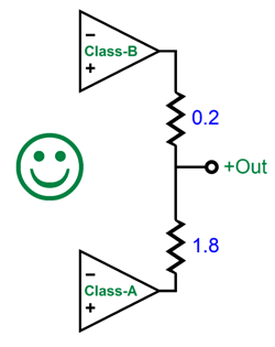
The 1.8-ohm resistor is nine times larger in value than the 0.2-ohm resistor, so the class-B amplifier will deliver (0.2 + 1.8) / 0.2 times more current than the class-A amplifier, which effectively makes an 8-ohm loudspeaker appear as an 80-ohm loudspeaker to the class-A amplifier (actually, it's 81.8 ohms). But with the 1-to-9 skewed resistor values, the class-A amplifier must produce nine times the inverted distortion produced by the class-B amplifier. For example, if the class-B amplifier puts out 10mV peak of distortion, then the class-A amplifier must deliver -90mV peak of distortion, which would sum to zero at the loudspeaker. How do we get the class-A amplifier to perform this task?
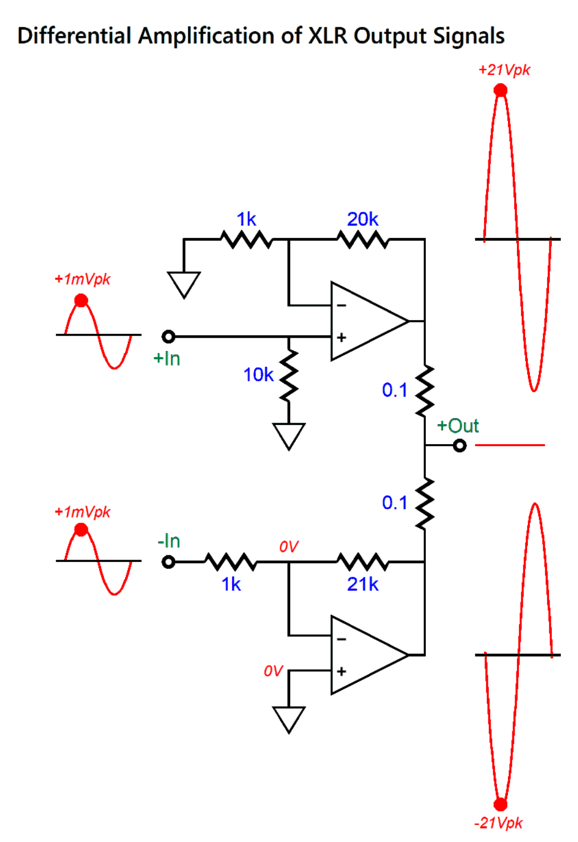
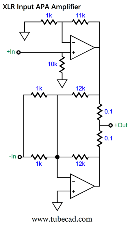
We will get there, but we must next bring back XLR balanced input signals. The important assumption here is that the balanced signals are truly balanced, so much so that their outputs will actually sum to zero.

By the way, you can buy even higher tolerance resistors that sport 0.01% tolerances. With true balanced signals, we can develop some fun arrangements. For example, we can create a power differential amplifier.
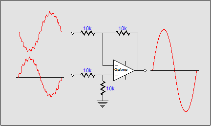
A differential amplifier only amplifies differences. Signals that are shared and in phase to each other, such as most induced noise, do not get amplified.
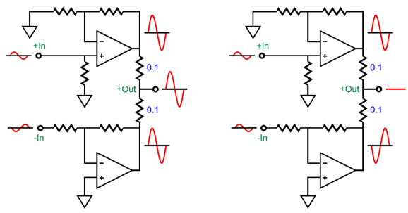
The solid-state two-amplifier differential amplifier shown above is not as elegant as a single differential amplifier. In fact, it is a brute-force differential amplifier. When presented with a common-mode signal (i.e. same phase), both amplifiers still amplify the signal, but as the two outputs are out of phase with each other, they cancel after passing through the two resistors. Effectively, each amplifier is working into a 0.1-ohm load. Ouch! Here is an example.
A tiny 1mV amount of in-phase hum enters the two amplifiers, and each amplifies the by its gain, 1:21 and 1:-21. Each amplifier must deliver 210mA of peak current into its 0.1-ohm resistor. In contrast, a single differential amplifier would simply ignore the 1mV of hum. So, is this arrangement not worthwhile? Not necessarily. The danger of large in-phase extraneous signals arises from the balanced signal source and the long balanced interconnect used. Well, what if we use neither?
%20Phase%20Splitter%20with%20LF%20&%20HF%20Filters.png)
We can build into the brute-force differential amplifier with its own phase splitter. Since we have added 6dB of gain, the net gain of the two-amplifier arrangement has gone from 1:21 to 1:42. Of course, we can also make a unity-gain phase splitter.
%20Phase%20Splitter.png)
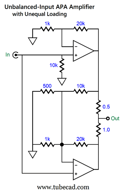
The input two-resistor voltage divider halves (-6dB) the input unbalanced signal, while the phase splitter still applies 6dB of gain, resulting in unity-gain. Using either of these phase splitters allows us to sidestep the problem of common-mode signals sneaking in, but it means that we have also lost the differential-amplification advantages. Okay, so far, it looks like using this arrangement offers little—do not give up yet. Let's start with returning to the design from post 594 that exploited the balanced signals from XLR output jacks.
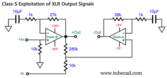
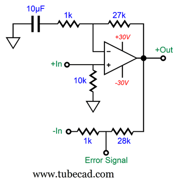
The tacked-on two-resistor voltage divider made up from the 280k and 10k resistors allows us to separate the distortion from the rest of the output signal from the class-B amplifier. If the class-B amplifier produces zero distortion, nothing will appear at the attenuator's output, as the inverted input signal perfectly nulls the amplified non-inverted output from the amplifier. By the way, we can use different attenuator resistor values, as long as they adhere to the same ratio.
Now that we have extracted the distortion, we can use it by delivering to an inverting amplifier. Since two 0.1-ohm output resistors are used in the following design example, the bottom inverted power amplifier must deliver the same amount of distortion as the class-B non-inverting power amplifier produces—but in anti-phase. Let's use a unity-gain buffer to relay the distortion signal to the inverting amplifier.
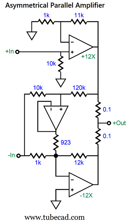
The OpAmp acts as a unity-gain buffer and drives the 923-ohm resistor. The bottom power amplifier performs two functions: it amplifies and inverts the XLR's inverted input signal; second, it also amplifies and inverts the class-B amplifier's distortion at its output, which allows the distortion null to obtain. Let us say that the class-B amplifier produces a +13mV DC offset at its output, which is a form of distortion, as no offset voltage appeared at its input.
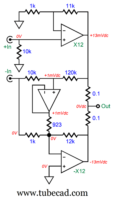
The two-resistor voltage divider that spans from the class-B amplifier's output to the XLR's inverted output reduces the 13mV to 1mV. The buffer passes along the 1mV through the 923-ohm resistor to the bottom inverting power amplifier, which in turn amplifies the 1mV to -13mV. Obviously, +13mV added to -13mV equals 0V. If you are wondering why a 923-ohm resistor was used, the answer is that 12k divided by 13 equals 923. But as they do not make 923-ohm resistors, we can place 1k and 12k resistors in parallel to get 923 ohms. (By the way, the assumption has been that super-tight tolerance resistors are used throughout. In other words, no 5% and 10% carbon-composition are allowed. Even 1% metal-film resistors are too slack in tolerance.)
Returning to 923 ohms of resistance and parallel resistors, the very second I thought of using the parallel resistors, my mind flashed that the unity-gain buffer was not needed, as we could use 1k and 12k as the two-resistor voltage divider resistor values.
This arrangement yields the same result, but does away with the buffer. Indeed, we can also replace the two 1k resistors in parallel with a 500-ohm resistor. Notice how the two-resistor voltage divider acts like a secondary negative feedback loop that injects the distortion from the top amplifier into the bottom amplifier's negative-feedback loop.
How well does this APA topology work? I ran SPICE simulations and witnessed a -60dB reduction in distortion, which translates into a thousand-fold improvement. Pause and wonder just how I could run such simulations. I used the SPICE model for the Ideal OpAmp for the bottom amplifier. Do not be fooled by the label "OpAmp," for when SPICE says ideal it means ideal. This not your father's OpAmp, as it can deliver 100A in 8milliohm loads! As for the class-B amplifier at the top, I also used the SPICE ideal OpAmp model, but with the injection of addition of harmonics—all the way up to the 8th harmonic, with each succeeding harmonic being 20dB down relative to its preceding harmonic. The THD came in at 1.0046% at all output levels.
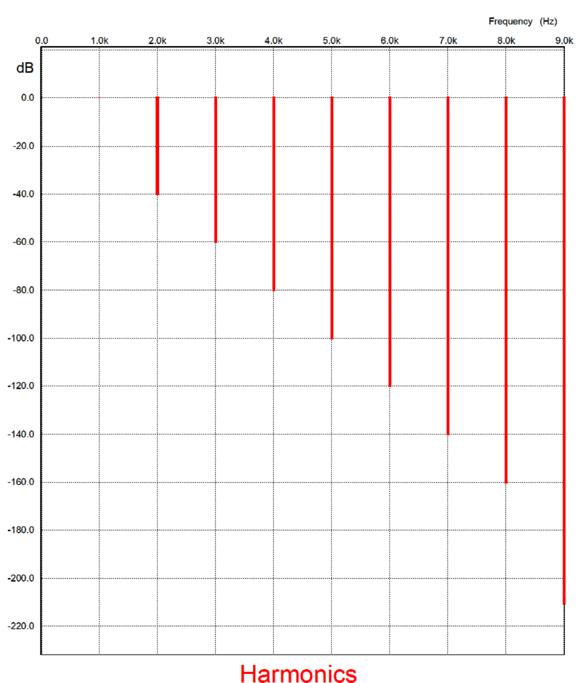
Without the added harmonics, all the harmonics would fall to the floor of the SPICE's Fourier-analysis, a bit below -200dB. A signal 200dB lower in amplitude is 1/10 10 as large, or one ten-thousandth of a million. (By the way, if I ever encountered a class-B amplifier that could deliver such a lovely single-ended-like cascade of harmonics, I would buy it in an instant.)
Put differently, this SPICE model is only a tool in simulation, not reality. In addition, the consistent 1.0046% THD at all output levels is a further huge departure from real solid-state class-B amplifiers, as real class-B amplifiers usually produce some distortion at low levels and improve with increased output. For example, here one THD graph for the beloved LM3886.
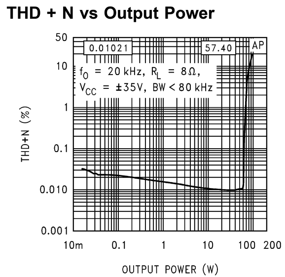
Note that the distortion steadily falls with increased output up to about 50W, after which it skyrockets. (In contrast, tube amplifiers, especially single-ended tube amplifiers, usually produce their least distortion at the lowest levels of output and then, fairly linearly, increase in distortion with greater output.)
Okay, let us now return to how the two-resistor voltage divider acts like a secondary negative feedback loop that injects the distortion from the top amplifier into the bottom amplifier's negative-feedback loop. As I stared at the topology, it hit me that we do not need the XLR's balanced input signals after all. All we need is the two sets of negative-feedback loops.
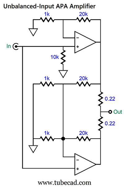
Note that the output resistors are the same value (0.22-ohms), which means that both amplifiers work equally in delivering current into the load and that the load impedance is effectively halved. For example, if an 8-ohm loudspeaker is driven, each amplifier effectively sees a 16-ohm load impedance (plus 0.22 ohms). Well, there's not much point to this equitable arrangement, as a perfect bottom amplifier can only halve the distortion created by a top dirty amplifier. On the other hand, if we use different-valued output resistors, we alter the current demands on each amplifier. Let's start simple and make the top amplifier work twice as hard as the bottom amplifier.
Both amplifiers deliver the same gain (1:21 or 26.44dB), but the top amplifier sees a 12.5-ohm load, while the bottom amplifier sees a 25-ohm load. (By the way, 12 ohms in parallel with 24 ohms equals 8 ohms.) For example, if the 8-ohm loudspeaker sees 36W of power (i.e. 24Vpk and 3Apk), the top amplifier delivers 2Apk; the bottom amplifier, 1Apk.
What we need is a flowchart of sorts to help us do the required math; thus, here it is.
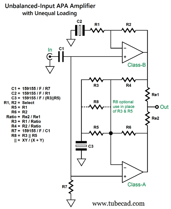
Capacitor C1 is either a polypropylene or PIO, while capacitors, C2 and C3 are non-polarized electrolytic. Here is a design example with an output-resistor ratio of 1:5.
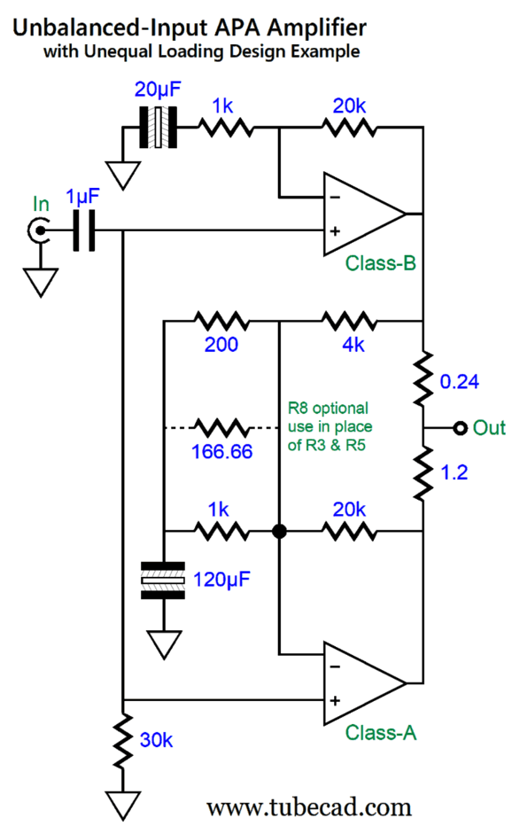
Note how the output resistor ratio is 1 to 5, which means that the bottom amplifier delivers one sixth the current that the loudspeaker sees while the top amplifier delivers the remain 5/6ths (83.3%). Also note how the 4k negative feedback resistor is 1/5th as large in resistance as the 20k negative feedback resistor, which means that the bottom amplifier will treat the top amplifier's output indiscretions with five times more effort, which will overcome its output resistor being five times larger in value. In other words, the top amplifier's distortion gets inverted and amplified fivefold by the bottom amplifier, thereby nulling at the loudspeaker connection.
By the way, making an inverting version is easy enough. All we have to do is use three negative-feedback loops: one for the top amplifier and two for the bottom amplifier.
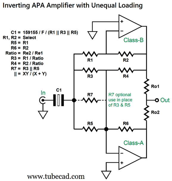
If nothing else, we have two fewer capacitors. But there is something else: most solid-state OpAmp and power amplifiers produce less distortion in the inverting configuration, as it reduces input stage common-mode distortion generation. Moreover, an inverting amplifier is less likely to suffer from positive feedback caused by the input signal being tainted by the output signal. If some mixing does happen, it just adds to the negative feedback. The supreme penalty we must pay is a much-lower input impedance. Okay, let's look at a fleshed-out design example.
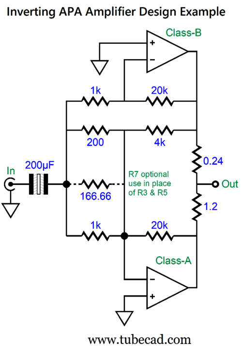
The input coupling capacitor has to be huge in value, as the amplifier's input impedance is a brutally low 143 ohms. The workaround is to add an inverting input buffer.
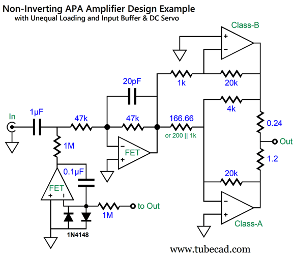
The input impedance is a relatively high 45k, and the input coupling capacitor is a reasonable 1µF. The DC servo eliminates any DC offset at the loudspeaker connection.
We can even eliminate the DC servo by using the OpAmp as both an inverting buffer and as a DC servo—but it does make me a tad nervous.
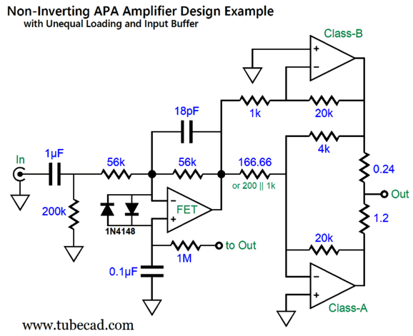
What makes me nervous is having the 0.1µF capacitor replace a direct connection to ground. In addition, the OpAmp gets its reference to ground through a passive 256k of resistance. By the way, note that the input inverting buffer imposes both a low-pass filter and a high-pass filter on the input signal, which is a good thing. (Of course, the top and bottom amplifiers often impose their own high-pass filter action with their negative feedback loop capacitors.)
How well, in general, does this asymmetrical-parallel arrangement work?
I mentioned before that SPICE simulations revealed a -60dB reduction in distortion. Thus, this aspect of the arrangement looks good. What I discovered, however, is that if the top amplifier presents a lot of distortion, the bottom class-A amplifier must do a lot more work. Lots more. How much is a lot?
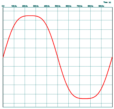
SPICE simulations revealed that 1% of 3rd harmonic distortion was enough to alter substantially the current division between amplifiers. For example, the APA amplifier shown above uses a 1-to-5 ratio of output resistors, so the top amplifier should deliver five times the current than the bottom amplifier. With the top amplifier producing just 1% of 3rd harmonic distortion, the output current ratio falls from 5-to-1 to 3-to-1, as the graph below shows.
As I have mentioned many times before, 3rd harmonic distortion compresses the output signal, so the bottom class-A amplifier must uncompressed the output signal, and that requires bigger current swings. The punch-line here is that the top class-B amplifier should be low-distorting to start with.
I am reminded of what I read in a dog-training book. The author told of an incident wherein he explained to a dog owner that he could be physically firmer with his dog. The owner then later picked up his small dog and hurled his dog into a wall, resulting in a visit to the veterinarian. "But you told me that I could be firmer."
The whole point behind this topology is that the bottom, class-A amplifier cleans up the top amplifier's mess, but the mess should be as small as possible. In other words, we do not have a license to make the dirtiest class-B amplifier possible. A good analogy might be trying to filter water: the cleaner the water going into the filter, the better the results.
In order to make sure that this APA topology held merit, I decided to forgo the use of the SPICE model of an Ideal OpAmp; instead, I used the SPICE model of the lowly LM741 for the top amplifier and the SPICE model of the LT1365 OpAmp for the bottom amplifier. The LT1365 offers a bandwidth of 70MHz and a 1000V/µs slewrate; the LM741 is about a thousand times worse. I used the 1-to-5 output resistor ratio and 60-ohm load to make the LM741 suffer. Here are the results.

We didn't get a 60dB improvement, save for the 7th harmonic. Nonetheless, the improvement is substantial.

To test the APA design in reality, I would start small. For example, I would build a headphone amplifier based on the APA concept, using an LM1875 for the top amplifier and a good OpAmp, such as the OPA637, for the bottom amplifier. If this small APA amplifier passes all the tests, then we build a power amplifier with ±35Vdc power-supply rails and an LM3886 as the top amplifier and a custom class-A amplifier for the bottom amplifier. With an output resistor ratio of 1-to-5, the LM3886 will see 8-ohm loads as 9.6 ohms, while the class-A will see a 48-ohm load. A push-pull class-A output stage that works under these power-supply rail voltages (and into this load impedance) need only idle at 400mA, which implies an idle dissipation of 28W. We could get extra fancy and build a single-ended class-A amplifier instead, which would idle at 0.8A, thereby doubling the dissipation at idle.

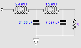
Undoing the prior-art attribution in post 510, I found, in Richard H. Small's 1971 paper in the JEAS, "Constant-Voltage Crossover Network Design," the following schematic.
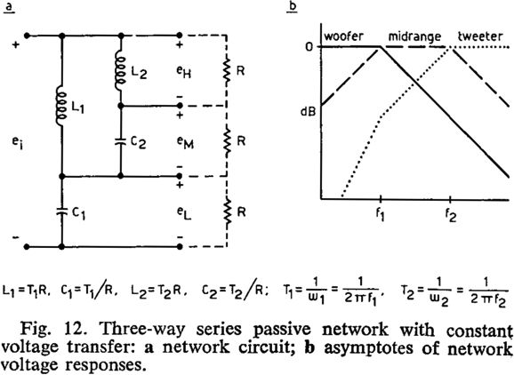
Note the tweeter cascade of cut-off slopes.
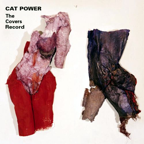
After my last music recommendation, Marc Cohn's Listening Booth 1970, I was on the hunt for other interesting albums of covers of famous songs. Chan Marshall's stage name is "Cat Power." I have only recently discovered her in my quest for new singers to hear, and I look forward to listening to all her albums. In order to get hooked, just listen to her cover of The Stones' major hit, "(I Can't Get No) Satisfaction." Unbelievable. If you didn't speak English, you would never guess that she was singing the 1960's anthem of sexual frustration and youthful exuberance thwarted by mass-market commercialism. She manages to transform the song into a mournful and fatalistic dirge of sorts. Amazing and truly compelling.
Alas, Amazon Music Service only offered this album in 16-bit, 44.1kHz. Nonetheless the sound recording is more than good enough.
//JRB
Did you enjoy my post? Do you want to see me make it to post 1,000? If so, think about supporting me at Patreon.

Just click on any of the above images to download a PDF of the user guides.
For those of you who still have old computers running Windows XP (32-bit) or any other Windows 32-bit OS, I have setup the download availability of my old old standards: Tube CAD, SE Amp CAD, and Audio Gadgets. The downloads are at the GlassWare-Yahoo store and the price is only $9.95 for each program.
http://glass-ware.stores.yahoo.net/adsoffromgla.html
So many have asked that I had to do it.
WARNING: THESE THREE PROGRAMS WILL NOT RUN UNDER VISTA 64-Bit or WINDOWS 7, 8, and 10 if the OS is not 32-bit or if it is a 64-bit OS.
I do plan on remaking all of these programs into 64-bit versions, but it will be a huge ordeal, as programming requires vast chunks of noise-free time, something very rare with children running about. Ideally, I would love to come out with versions that run on iPads and Android-OS tablets.
|
|
|
|
I know that some readers wish to avoid Patreon, so here is a PayPal button instead. Thanks.
John Broskie
John Gives
To all my patrons, all 85 of them, thank you all again. I want to especially thank
Concordio Anacleto
Walter Clay
King Heiple
Kuldeep
Amy D. McNeil
Paul Radovan
Christian Rintelen
Jason Stoddard
Kelvin Tyler
Dwight Warren
I am truly stunned and appreciative of their support. In addition I want to thank the following patrons:
John Atwood
Hal Clark
Dean Bailey
Jim Burnes
Eduardo Fayad
Scott Fraser
Manny Gagliano
Mike Galusha
Richard Hansen
Andreas Hierzenberger
Erik Hoel
Dean Kayser
Tom Kelly
Thomas Kifowit
Francis King
Frank Klapperich
Neil Kovacs
Przemek Lach
Robert
Ron Lee
偉良 林 (David Lin)
Amy D. McNeil
Csaba Molnar
Joe Mooney
John R. Murray
Seiichiro Nakakura
Larry Owens
John Puma
Paul Reid
Marty Reiss
Paulo Mario dos Santos Dias de Moraes
Blake Swaney
Michael Taylor
Brian Terrell
James Tiemann
Dwight Warren
Andrew White
Sergey Yegourno
All of your support makes a big difference. I would love to arrive at the point where creating my posts was my top priority of the day, not something that I have to steal time from other obligations to do. The more support I get, the higher up these posts move up in deserving attention.
If you have been reading my posts, you know that my lifetime goal is reaching post number one thousand. I have 409 more to go.
My second goal was to gather 1,000 patrons. Well, that no longer seems possible to me, so I will shoot for a mighty 100 instead. Thus, I have just 15 patrons to go.
Help me get there. Thanks.
Only $9.95
to start designing
tube-based crossovers
and much more...
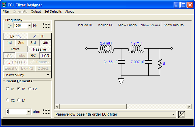
TCJ Filter Design
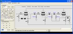
The Tube CAD Journal's first companion program, TCJ Filter Design lets you design a filter or crossover (passive, OpAmp or tube) without having to check out thick textbooks from the library and without having to breakout the scientific calculator. This program's goal is to provide a quick and easy display not only of the frequency response, but also of the resistor and capacitor values for a passive and active filters and crossovers.
TCJ Filter Design is easy to use, but not lightweight, holding over 60 different filter topologies and up to four filter alignments:
Bessel,
Butterworth,
Gaussian,
Linkwitz-Riley.
While the program's main concern is active filters, solid-state and tube, it also does passive filters. In fact, it can be used to calculate passive crossovers for use with speakers by entering 8 ohms as the terminating resistance. Click on the image below to see the full screen capture.
Tube crossovers are a major part of this program; both buffered and un-buffered tube based filters along with mono-polar and bipolar power supply topologies are covered. Available on a CD-ROM and a downloadable version (4 Megabytes).
|