| John Broskie's Guide to Tube Circuit Analysis & Design |
13 February 2024 Post Number 596
Happy Chinese New Year
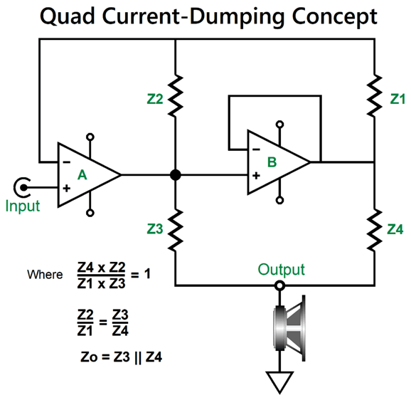
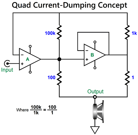
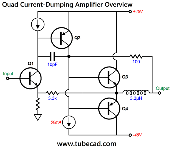
Quad Current-Dumping Topology The Quad design makes use of a true class-B output stage, as its output devices draw no current at idle (think of it as being closer to a class-C output stage, if you like). This feature is what makes the amplifier so compelling from the manufacturer's point of view. Setting a push-pull solid-state output stage's optimal output-device idle current is a major pain, especially with bipolar transistors, as the target moves with temperature change and trim potentiometer setting can alter in shipping—yet getting the bias voltage right is essential to getting low-distortion output. In contrast, class-A output stage are relatively easy to bias, as the average current conduction while driving the loudspeaker is the same amount as the idle current. In contrast, tube-based output stages are supremely forgiving in comparison. (The same holds largely true for MOSFET-based output stages, especially with lateral MOSFETs, due to the high idle current required.) The big problem with class-B output stages is distortion, lots of it, especially at low output, as the output devices must be summoned from their deep sleep and provoked into active duty. The class-A output stage is meant to fill in this gap. To achieve this goal, the Quad current-dumping amplifier cleverly makes use of a Wheatstone-bridge network both to provide two current paths to the loudspeaker, one from the class-A output stage and one from the class-B output stage, and to provide a negative feedback loop for the amplifier.
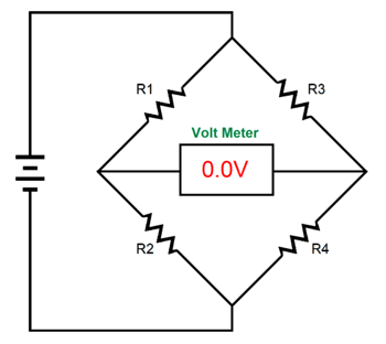
With a bridge circuit, balance (i.e. zero voltage) obtains when R2/R1 equals R4/R3. If we don't know the value of resistance R4, but if we do know the values of R1 & R2 and if we make R3 adjustable, we can then find the value of resistance R4 by using the following formula: R4 = (R3 x R4)/R1 Alternatively, we can use Kirchhoff's laws to translate the voltage reading into resistance. The Quad current-dumping amplifier uses four impedances in place of four resistors. In other words, it holds a capacitor and an inductor.
The amplifier on the left is a low-distortion, low-power class-A output stage, while the amplifier on the right is a high-distortion, high-power class-B amplifier. As configured, both amplifiers operate as unity-gain power buffers. To create a voltage amplifier, we need only add one resistor. In Walker's article on the current-dumping amplifier in the December of 1975's issue of Wireless World, the following resistor values are given as an example. If both amplifiers are putting out the same output voltage, the class-B amplifier must be delivering 99% of current into the loudspeaker, hence the name: "current-dumping amplifier."
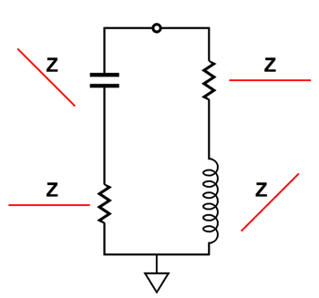
A Wheatstone bridge can be made not only from four resistors, but four reactive devices, such as capacitors and inductors—as long as the math still holds. In fact, capacitors, inductors, and resistors can be used in the bridge circuit. Quad used such a mixed bridge in their current-dumping amplifier.
The secret to understanding this arrangement is not to think in terms of capacitance and inductance, but in terms of impedance. For example, a 10pF capacitor represents a tiny amount of capacitance, but a huge impedance at audio frequencies; a 3.3µH inductor also presents a small amount of inductance, but it also presents a small impedance at audio frequencies. As frequency rises, a capacitor's impedance falls, while an inductor's impedance rises. In contrast, as frequency falls, a capacitor's impedance rises, while an inductor's impedance falls.
Note that if we overlay the capacitor's impedance plotline atop the inductor's, the two slopes would sum to flat.
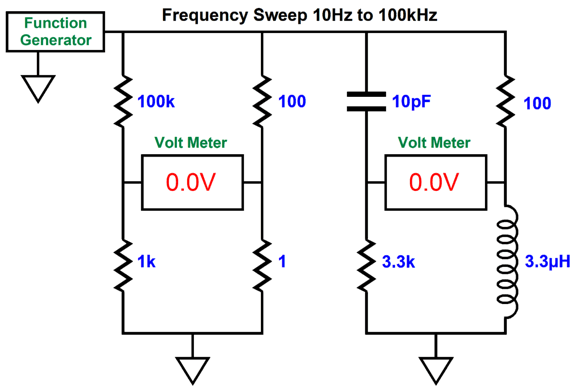
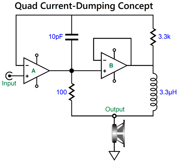
With the function generator producing a sweep of frequencies from 1Hz to 100kHz, both voltage meters read zero volts, as both Wheatstone bridges are in balance. By the way, the capacitor and inductor values are those that Walker provided in his article as design example.
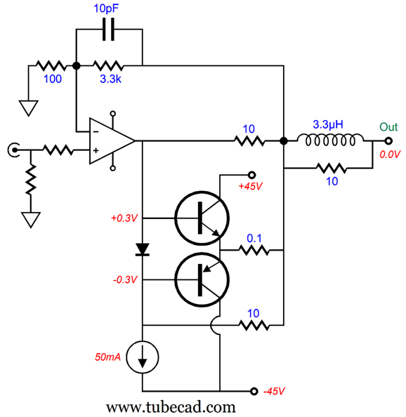
These values balance the Wheatstone bridge, in conformance to Walker's formula: L = RRC If you multiply the resistances against each other and then against the capacitance, you will get 3.3µH of inductance. (Remember that one pico-farad [pF] is one trillionth of one farad, i.e. 10 to the –12 power.) Because the bridge is balanced, the signal that appears at the class-A amplifier's inverting input must equal the signal at the output that the loudspeaker uses. What follows is a simplified version of the core of the Quad current-dumping amplifier.
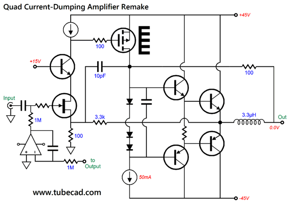
Transistors Q1 and Q2 define the class-A amplifier, a single-ended amplifier at that. The 50mA constant-current source sets its idle current. Transistors Q3 and Q4 define the class-B output stage. At idle, transistors Q3 and Q4 draw no current. No current, no heat. In contrast, the class-A single-ended output stage will dissipate 4.5W. (Long ago, I built and designed a fairly conventional solid-state power amplifier that held a similar departure from established practice in that the driver stage idled at twice the current than did the output stage. An EE friend heard my amplifier and fell in love with the silky high-frequency response. He wanted the schematic, as he had to build one for himself. He called me to inform me that I must have transposed the current values, as the output transistors idled at 50mA, while the driver transistors idled at almost 100mA; surely, I had them backwards, he thought. I explained that I didn't, that I had to run that high a driver current to get the silken highs he so delighted in. He never built the amplifier, as he could not tolerate the departure from established practice: i.e. 2mA for the differential input stage, 5mA for the VAS stage, 10mA for the emitter-follower driver stage, and 100mA for the output transistors. By the way, lest you think that only solid-state practitioners are so mentally straightjacketed, I have encountered similar mental roadblocks from tube-loving folk. I remember being told that I could not follow an octal input tube with a noval driver tube, as the progression had to be smaller tube to bigger tube. I pointed out that I was going from weaker transconductance to stronger transconductance. Apparently, that didn't matter, as the important feature was the size of the glass envelope.) Today, we would get extra fancy, using a cascoded input FET in place of the NPN transistor and a few other enhancements:
The three diode voltage drops should be enough to bias the driver transistors, but not enough to turn on the output transistors. The DC servo eliminates any DC offset at the output, while the input coupling capacitor filters away any DC offset voltage present on the input signal. With the bipolar power supply voltages, we should be able to get an easy 80W of output into an 8-ohm load. The actual Quad current-dumping amplifier schematic will probably make your head hurt.
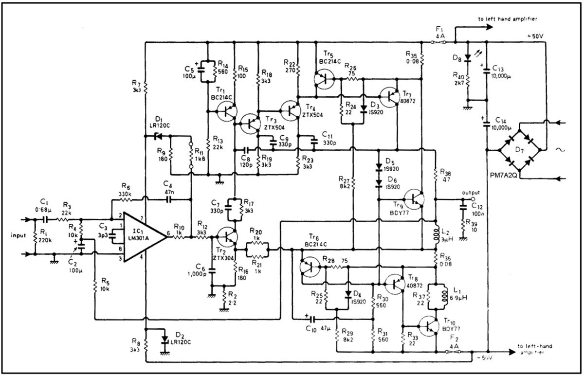
The LM301A OpAmp functions as both a preamplifier and as a DC servo. The OpAmp does not, however, receive any AC negative feedback from the amplifier's output, only DC feedback, as capacitor C2 shunts away the audio frequencies. Transistor Tr2 performs the negative feedback task. This is the schematic that appeared in Walker's article in Wireless World, but I am not convinced that it doesn't hold a few typos. How well does the Quad current-dumping amplifier topology work? It works, but so does all the same parts arranged in the more conventional topology.
This is a common topology that boosts an OpAmp's current output. I don't much like it, however, as I prefer my alternative arrangement.
Not shown is the power MOSFET or power NPN transistor within the amplifier's triangle symbol that draws 50mA from the constant-current source. In other words, this is a class-A single-ended amplifier both driving and being in parallel with a class-B, push-pull output stage. The two 10-ohm resistors are effectively in parallel, making a combined resistance of 5 ohms. The current ratio split between class-A and class-B will be 1 to 50, as 5/0.1 = 50.
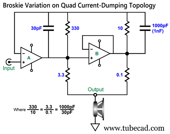
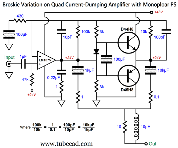
Broskie Variation on Quad Current-Dumping Topology
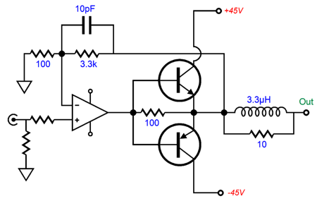
The extra capacitors are there to ensure amplifier stability at high frequencies. Since the bridge is concerned with impedances, the capacitors' impedances conform to the same ratio as the resistors. This amplifier's output impedance is 0.097 ohms, which implies a damping ratio of 82. There's no need to sigh, as many great sounding tube-based single-ended power amplifiers sport output impedances of 2 ohms or greater. This schematic shows a power buffer, not a voltage amplifier. To convert the circuit into a signal amplifier requires one additional resistor.
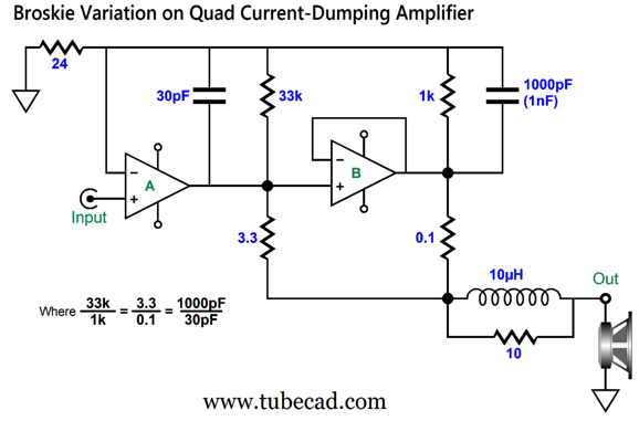
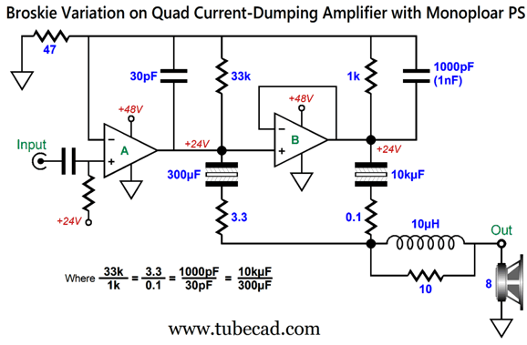
The 1k and 33k resistors are effectively in parallel, making 970 ohms of resistance, which working with the 24-ohm resistor implies a voltage amplification of 1:41.4, as (970 + 24)/24 = 41.4. I threw in the output inductor, which shields the amplifier from heavy capacitance-laden loads. (The 10-ohm resistor shunting the inductor is a good idea as it prevents inductor-induced oscillations at the loudspeaker.) The 0.1-ohm resistor could be used as part of a current-limiting circuit, which would come in handy if the output were shorted to ground—something we could not do with an inductor. Here is another idea: the same amplifier, but for use with a monopolar power supply, say a 48Vdc switcher.
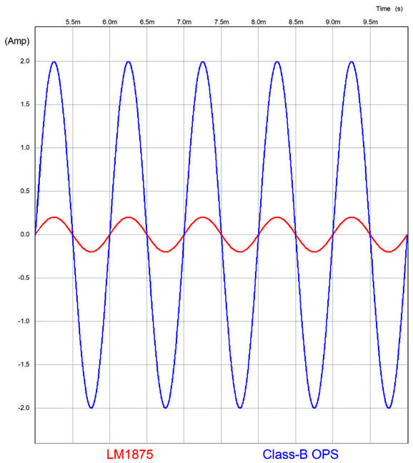
In place of output resistors, we have output capacitors, capacitors that conform to the same impedance ratio. Here is a design example that makes use of the LM1875, not a class-A amplifier to drive a class-B output stage.
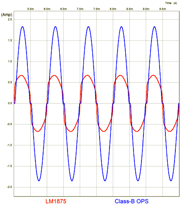
The LM1875, a 5-pin TO-220 IC amplifier, takes care of its own idle-current draw, while the NPN and PNP class-B transistors draw no current at idle. The LM1875 is a fun little amplifier, but it is handicapped by its small package, which creates a relatively high thermal resistance (θ JC = 2°C/W). No doubt, had the LM1875 been packaged in the TO-247 case, it would have found greater use. The addition of the class-B output stage unloads the LM1875 and makes driving 4-ohm loads easy. One big advantage of using a monopolar power supply is that the LM1875, like most OpAmps, offers far better positive-power-supply pin PSRR than at its negative power-supply pin. In this arrangement, the negative pin is directly grounded, so only the positive-rail PSRR remains. In addition, the output coupling capacitors make the amplifier safe from a shorted output. (As far as I know, they do not make non-polarized capacitors in 10kµF. The workaround would be to use two 20kµF polarized capacitors in series, but bypassed with either a non-polarized capacitor or large-valued film capacitor. The 10-to-1 output resistor ratio seems to imply that the LM1875 delivers 10% of the output current flow. SPICE simulations, however reveal a different story. Up to 2Vpk of output voltage swing into an 8-ohm load, all the current flow is entirely from the LM1875. At 20Vpk (25W into 8-ohms), the LM1875 delivers 36% of the current.
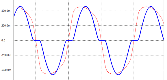
At around 7Vpk, they both put out equal flows of current. In short, the higher the output voltage swing (and the current swing), the closer we get to the 1-to-10 current ratio. What is going on here is that the class-B output stage actually runs in class-C, as it is turned off during a portion of the output waveform. Let's take a closer look at the class-B's current delivery at 7Vpk of output into 8 ohms.
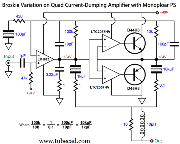
You can see the flat-line current conduction in the class-B output stage. If we employ something closer to actual Class-B operation, wherein the output devices instantly turn on as input signal demands, then we do get the 1-to-10 current division. One possible arrangement is to use two high-voltage OpAmps to control the output transistors.
The high-voltage OpAmps force zero current conduction from the class-B transistors at idle, yet they can instantly turn on these transistors in the presence of input signal. Here is the SPICE-generated current-conduction graph for the above circuit at 20Vpk of output into an 8-ohm load.
Now, we see the 1-to-10 current ratio. (This assumes no distortion from the class-B output stage, however, as 3rd harmonic distortion from the class-B transistors will force more current flow from the LM1875.)
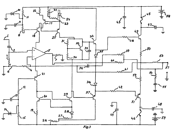
United States Patent US 8,988,145 B2
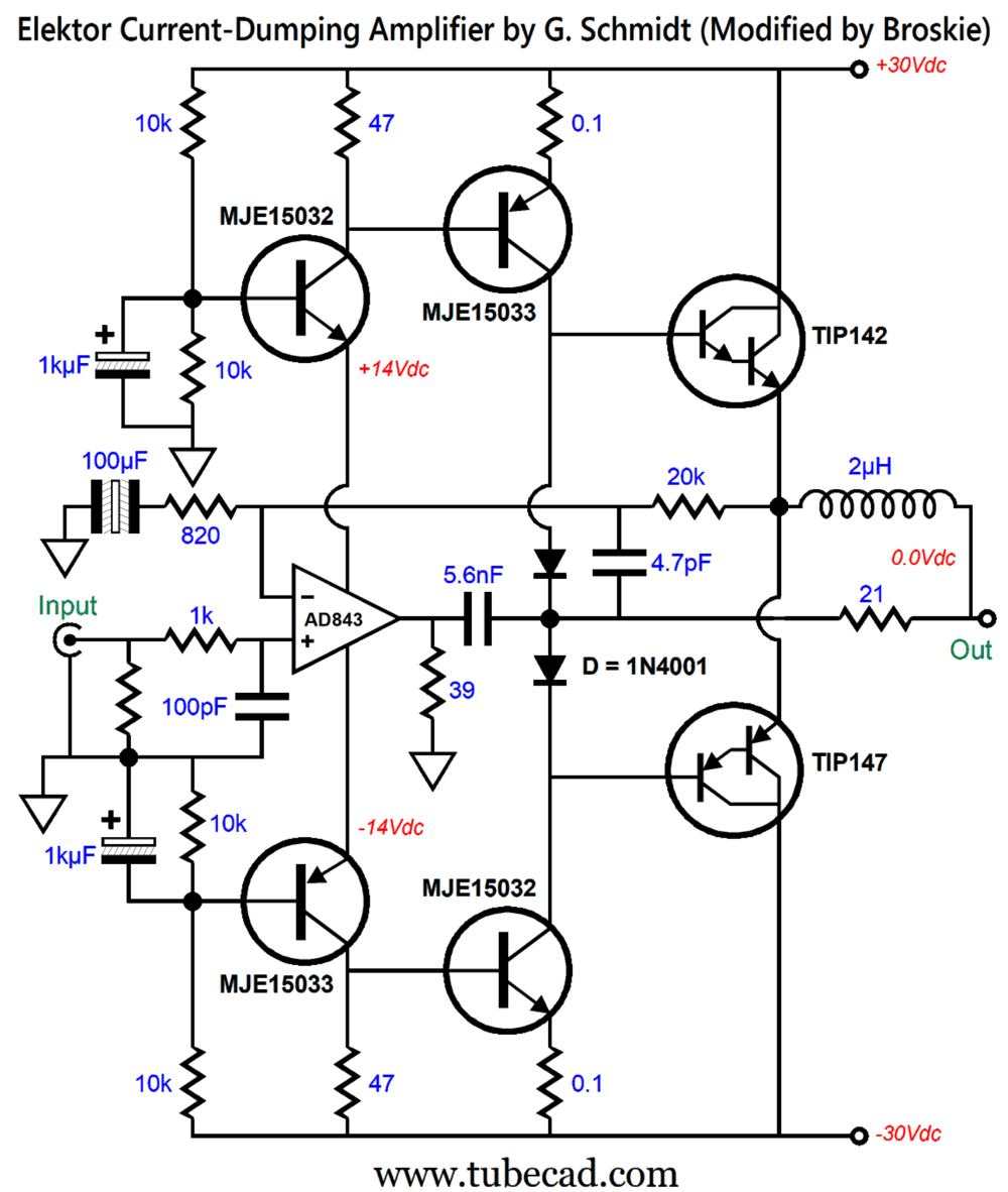
If looking at this schematic makes your eyes hurt, you are not alone. Worse, this is a cleaned up version, as the original was missing some connection lines, which I included in the schematic. In spite of the eyesore, I instantly was reminded of a current-dumping amplifier design from the 51/52 issue of Elektor magazine from 1979. 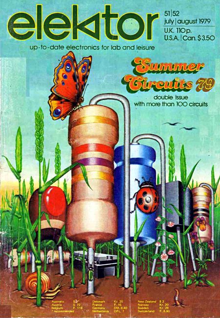
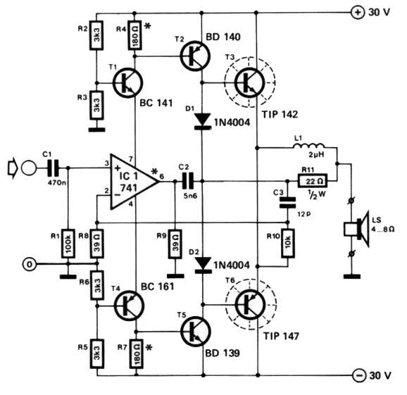
Click on cover to see PDF For decades now, I have wanted to run SPICE simulations on the design, but I could never quite summon the will to do so—until writing this post, that is. Here is the schematic from the magazine:
This current-dumping amplifier follows Quad's design principles, as components C3, L1, R10, and R11 conform to a balanced Wheatstone bridge, since L1 = C1 ·R10 ·R11. The class-B output stage is made up of the two diodes and transistors T3 and T6, both of which are Darlington types. Transistors T2 and T5 constitute the class-A amplifier stage. The humble LM741 is in charge. As it drives the 39-ohm load resistor, the current flow through its own output stage is relayed through the two cascode transistors, T1 and T4, to the 180-ohm resistors. The varying current flow creates a varying voltage drop across the resistors, which in turn drive the class-A output stage. Capacitor C2 helps stabilize the OpAmp by effectively providing high-frequency negative feedback. (In many ways, the 39-ohm load resistor (R9) is analogous to the cathode resistor in grounded-cathode amplifier.) I am convinced that resistor R8's value is a typo, as it should be 390 ohms, not 39 ohms. The SPICE model that I had for the LM741 was unusable in this circuit, as it did not include the actual varying current draw from the OpAmp's power-supply pins. (This is a common failing with many OpAmp SPICE models.) I used the AD843 model in place of the LM41's, as it worked and as I like the OpAmp in reality, owning many of them. Thus, I had to make a few part value changes to get a working simulation circuit. In order to get the optimal high-frequency stability from the AD843, I had to use a 4.7pF capacitor in the bridge network, which forced changes in resistor R10 and R11 values. I also added 0.1-ohm emitter resistors to the class-A output stage transistors.
In SPICE simulations, the amplifier put out an easy 40W into 8 ohms with better than 0.01% THD. The class-A transistors idle at 47mA, which implies a peak class-A output current swing of 94mA. At 40W of output, the class-A output stage delivered 41mA of peak current swing, while the class-B output stage delivered a tad over 3A of peak current flow. Okay, lets now return to Mr. Popescu's patent.
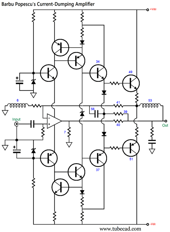
Prose worthy of the accompanying patent schematic—no doubt the original was more melliferous in the original Romanian. I have redrawn the schematic:
The zener in the center stands for the V be-multiplier circuit.
The design presents several odd features, for example, the inductor (marked 6) that terminates the negative feedback string of resistors. Usually a capacitor is used, as the capacitor allows the amplifier to use all its negative feedback to eliminate a DC offset at its output or, what is worse, the amplifier amplifying a DC offset in its input signal. In this circuit, the inductor will limit the high-frequency response. Another odd feature is the class-A transistors 34 & 37 get diodes, not emitter resistors. An emitter resistor presents form of negative feedback that prevents runaway current conduction. In other words, if the output transistor conducts too much current, the emitter resistor will see a greater voltage drop, which in turn will limit further conduction. A diode, not so much. Perhaps, his elaborate constant-current source scheme creates an auto-bias function for the class-A output stage, so the diodes are no longer a liability. (But in the absence of any large-valued capacitors to filter away the AC signal, I don't see how that would be possible.) A further odd feature is resistor 40, which might make sense, as it would function as a negative feedback loop of sorts. Do not forget that the OpAmp only swings a small output voltage, in spite of the huge output voltage swings at the amplifier's output.
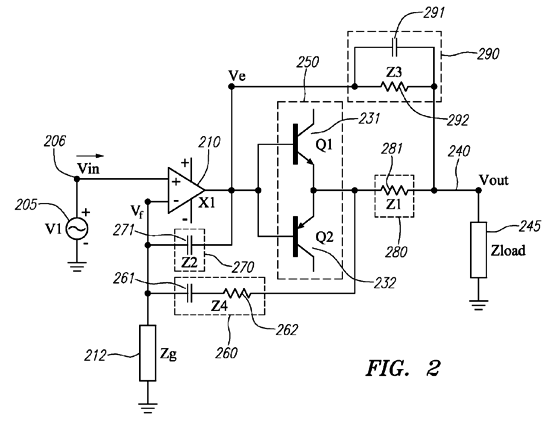
US Patent US 8,004,355 B2
I quite like the look of this current-dumping amplifier. I like how capacitor (Z2) providing high-frequency stability for the class-A input amplifier, as well as the inverse-parallel symmetry between Z3 and Z4. Moreover, no inductor is used in the feedback loop. The patent further outlines a cascaded version. Worth reading, in short.
Music Recommendation: Higher-Res Blues Singer //JRB
Did you enjoy my post? Do you want to see me make it to post 1,000? If so, think about supporting me at Patreon.
User Guides for GlassWare Software
For those of you who still have old computers running Windows XP (32-bit) or any other Windows 32-bit OS, I have setup the download availability of my old old standards: Tube CAD, SE Amp CAD, and Audio Gadgets. The downloads are at the GlassWare-Yahoo store and the price is only $9.95 for each program. http://glass-ware.stores.yahoo.net/adsoffromgla.html So many have asked that I had to do it. WARNING: THESE THREE PROGRAMS WILL NOT RUN UNDER VISTA 64-Bit or WINDOWS 7, 8, and 10 if the OS is not 32-bit or if it is a 64-bit OS. I do plan on remaking all of these programs into 64-bit versions, but it will be a huge ordeal, as programming requires vast chunks of noise-free time, something very rare with children running about. Ideally, I would love to come out with versions that run on iPads and Android-OS tablets.
|
I know that some readers wish to avoid Patreon, so here is a PayPal button instead. Thanks.
John Broskie
John Gives
Special Thanks to the Special 94 To all my patrons, all 94 of them, thank you all again. I want to especially thank
I am truly stunned and appreciative of their support. In addition I want to thank the following patrons:
All of your support makes a big difference. I would love to arrive at the point where creating my posts was my top priority of the day, not something that I have to steal time from other obligations to do. The more support I get, the higher up these posts move up in deserving attention.
If you have been reading my posts, you know that my lifetime goal is reaching post number one thousand. I have 406 more to go. My second goal was to gather 1,000 patrons. Well, that no longer seems possible to me, so I will shoot for a mighty 100 instead. Thus, I have just 16 patrons to go. Help me get there. Thanks.
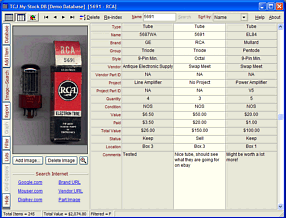
Only $12.95 TCJ My-Stock DB
Version 2 Improvements *User definable Download for www.glass-ware.com
|
|||


| www.tubecad.com Copyright © 1999-2024 GlassWare All Rights Reserved |